Publication 1746-UM022B-EN-P - January 2005
3-2 Considerations Before Using Your Module
Module Addressing
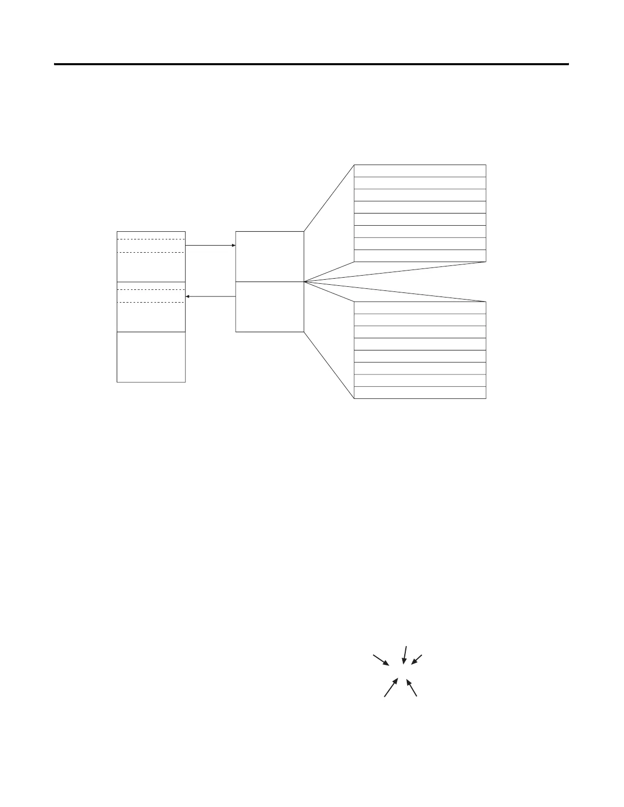
The following memory map shows you how the SLC processor’s
output and input tables are defined for the module.
Image Table
Output Image - Configuration Words
Eight words of the SLC processor’s output image table are reserved for
the module. Output image words 0 through 7 are used to configure
the module’s input channels 0 through 7. Each output image word
configures a single channel and can be referred to as a configuration
word. Each word has a unique address based on the slot number
assigned to the module.
Example Address - If you want to configure channel 2 on the
module located in slot 4 in the SLC chassis, your address would be
O:4.2.
Slot e
Output Image
Word 0
Word 1
Word 2
Word 3
Word 4
Word 5
Word 6
Word 7
O:e.0
O:e.1
O:e.2
O:e.3
O:e.4
O:e.5
O:e.6
O:e.7
Word 0
Word 1
Word 2
Word 3
Word 4
Word 5
Word 6
Word 7
I:e.0
I:e.1
I:e.2
I:e.3
I:e.4
I:e.5
I:e.6
I:e.7
Address
Address
Bit 15
Bit 15
Bit 0
Bit 0
Slot e
Input Image
Thermocouple
Module
Image Table
SLC 5/0X
Data Files
Output
Scan
Input
Scan
Output Image
8 Words
Input Image
8 Words
Channel 0 Configuration Word
Channel 1 Configuration Word
Channel 2 Configuration Word
Channel 3 Configuration Word
Channel 4 Configuration Word
Channel 5 Configuration Word
Channel 6 Configuration Word
Channel 7 Configuration Word
Channel 0 Data or Status Word
Channel 1 Data or Status Word
Channel 2 Data or Status Word
Channel 3 Data or Status Word
Channel 4 Data or Status Word
Channel 5 Data or Status Word
Channel 6 Data or Status Word
Channel 7 Data or Status Word
O:4.2
Slot
Word
Word
Delimiter
Element
Delimiter
File Type

 Loading...

