1 Publication 1746-UM022B-EN-P - January 2005
Chapter
1
Module Overview
This chapter describes the thermocouple/mV input module and
explains how the SLC 500 processor reads thermocouple or millivolt
analog input data from the module.
Read this chapter to familiarize yourself further with your
thermocouple/mV analog input module. This chapter covers:
• general description and hardware features
• an overview of system and module operation
• block diagram of channel input circuits
General Description
This module mounts into 1746 I/O chassis for use with SLC 500 fixed
and modular systems. The module stores digitally converted
thermocouple/mV analog data in its image table for retrieval by all
fixed and modular SLC 500 processors. The module supports
connections from any combination of up to eight thermocouple/mV
analog sensors.
Input Ranges
The following tables define thermocouple types and associated
temperature ranges and the millivolt analog input signal ranges that
each of the module’s input channels support. To determine the
practical temperature range of your thermocouple, refer to the
specifications in Appendix A.
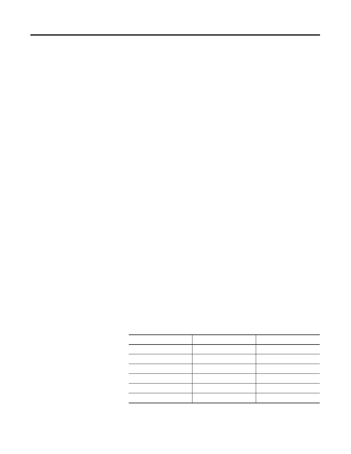
Thermocouple Temperature Ranges
Type °C Temperature Range °F Temperature Range
J -210°C to +760°C -346°F to +1400°F
K -270°C to +1370°C -454°F to +2498°F
T -270°C to +400°C -454°F to +752°F
B +300°C to +1820°C +572°C to +3308°F
E -270°C to +1000°C -454°F to +1832°F
R 0°C to +1768°C +32 F to +3214°F

 Loading...

