Publication 1746-UM022B-EN-P - January 2005
Module Overview 1-3
Hardware Features
Diagnostic LEDs
The module contains diagnostic LEDs that help you identify the
source of problems that may occur during power-up or during normal
operation. Power-up and channel diagnostics are explained in
Chapter 6, Testing Your Module.
System Overview
The module communicates with the SLC 500 processor and receives
+5V dc and +24V dc power from the system power supply through
the parallel backplane interface. No external power supply is
required. You may install as many thermocouple modules in the
system as the power supply can support.
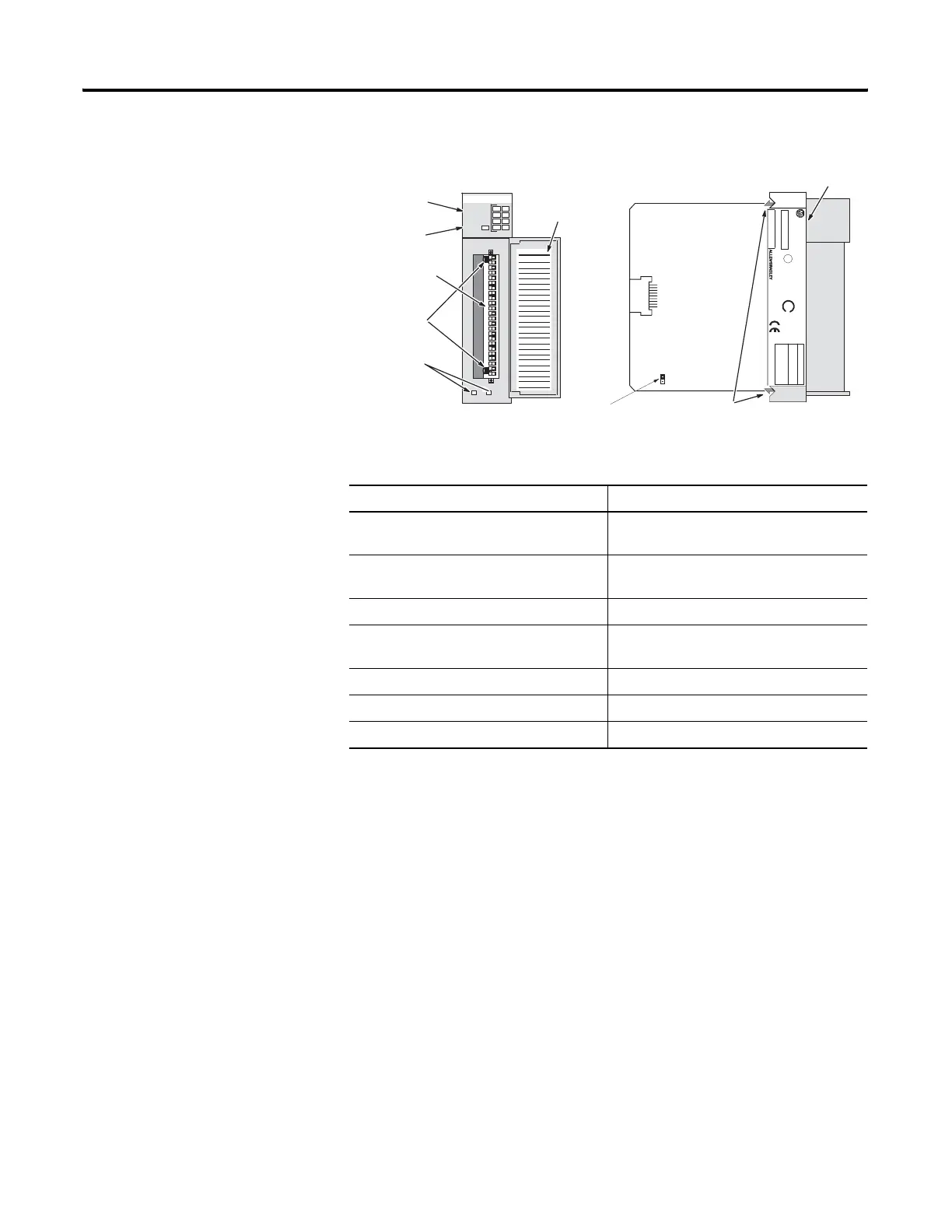
Hardware Function
Channel Status LED Indicators Display operating and fault status of
channels 0 to 7
Module Status LED Displays operating and fault status of the
module
Side Label (Nameplate) Provides module information
Removable Terminal Block Provides electrical connection to input
devices
Door Label Permits easy terminal identification
Cable Tie Slots Secure and route wiring from module
Self Locking Tabs Secure module in chassis slot
SLC 500
CAT
SERIAL NO.
THERMOCOUPLE/mV INPUT MODULE
MADE IN USAFAC 1M
INPUT SIGNAL RANGES
THERMOCOUPLE TYPES:
VOL TAGE:
±100mVDC to +100mVDC
±50mVDC to +50mVDC
SER
FRN
)
U
L
LISTED IND. CONT . EQ.
FOR HAZ. LOC. A196
CLASS I, GROUPS A, B, C AND D, DIV .2
OPERA TING
)
SA
J, K, T, E, R, S, B, N
TEMPERA TURE
CODE T3C
1746 NT4
NT4±xxx x
MODULE
0
1
4
5
2
1
2
3
CHANNEL
STATUS
THERMOCOUPLE/mV
INPUT
CJC A+
CJC A-
CHL 0+
CHL 0-
SHIELD
CHL 1+
CHL 1-
CHL 2+
CHL 2-
SHIELD
CHL 3+
CHL 3-
CHL 4+
CHL 4-
SHIELD
CHL 5+
CHL 5-
CHL 6+
CHL 6-
SHIELD
CHL 7+
CHL 7-
CJC B+
CJC B-
1746-NT8
JP1
Channel Status
LEDs (green)
Module Status
LEDs (green)
Removable
Terminal Block
CJC Sensors
Cable Tie Slots
Door Label
Jumper - Do not move
Self-Locking Tabs
Side Label

 Loading...

