1 Publication 1746-UM022B-EN-P - January 2005
Chapter
4
Channel Configuration, Data, and Status
Read this chapter to:
• configure each input channel
• check each input channel’s configuration and status
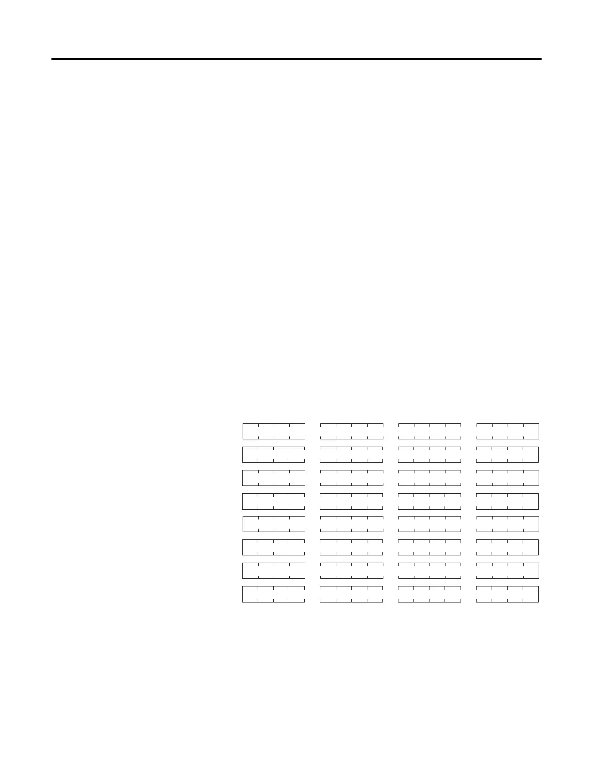
Channel Configuration
Channel configuration words appear in the SLC processor’s output
image table as shown below. Words 0 to 7 correspond to module
channels 0 to 7.
After module installation, configure each channel to establish the way
the channel operates (e.g., thermocouple type, temperature units,
etc.). Configure the channel by setting bits in the configuration word
using your programming device. The SLC configuration words are
shown below.
SLC Output Image (Configuration) Words
e = slot number of the module
bit 0
bit 15
O:e.0
O:e.1
O:e.2
O:e.3
O:e.4
O:e.5
O:e.6
O:e.7
Channel 0 Channel Configuration Word
Channel 1 Channel Configuration Word
Channel 2 Channel Configuration Word
Channel 3 Channel Configuration Word
Channel 4 Channel Configuration Word
Channel 5 Channel Configuration Word
Channel 6 Channel Configuration Word
Channel 7 Channel Configuration Word

 Loading...

