EasyManua.ls Logo

Allen-Bradley 1756-PA75 User Manual

Allen-Bradley 1756-PA75
12 pages
To Next Page IconTo Next Page
Page #1 background imageLoading...
Page #1 background image
Installation Instructions
Original Instructions
ControlLogix Power Supply
Catalog Numbers
1756-PA30XT, 1756-PA50, 1756-PA72, 1756-PA75, 1756-PB30XT, 1756-PB50, 1756-PB72, 1756-PB75, 1756-PC75, 1756-PH75,
1756-PAXT, 1756-PBXT
Product Overview
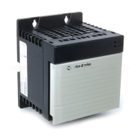
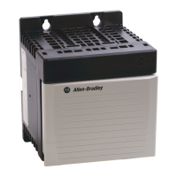
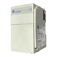
ControlLogix® power supplies are used with the 1756 chassis to provide 1.2V, 3.3V, 5V, and 24V DC power directly to the chassis backplane.
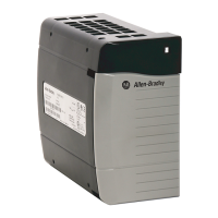
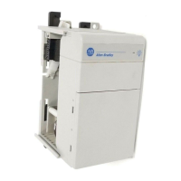
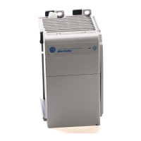
Standard, ControlLogix-XT™, and slim (reduced width) power supplies are available.
Topic Page
Tools Required 5
Power Supply and Chassis Compatibility 6
Install the Power Supply 7
Connect the Power 7
Remove the Protective Label 9
Troubleshoot the Power Supply 9
Specifications 10
Additional Resources 11
Question and Answer IconNeed help?

Do you have a question about the Allen-Bradley 1756-PA75 and is the answer not in the manual?

Allen-Bradley 1756-PA75 Specifications

General IconGeneral
Input Frequency47-63 Hz
Output Power75W
Output Voltage5.1V DC, 24V DC
Isolation Voltage1500V AC
Power Supply LocationChassis
Input Voltage85-265V AC
Operating Temperature0 to 60 °C
Storage Temperature-40 to 85 °C
Humidity5 to 95% (non-condensing)

Summary

Environment and Enclosure

Prevent Electrostatic Discharge

North American Hazardous Location Approval

European Hazardous Location Approval

IEC Hazardous Location Approval

Tools Required

Power Supply and Chassis Compatibility

Install the Power Supply

Connect the Power

Optional Power Cable Connection

Remove the Protective Label

Troubleshoot the Power Supply

Specifications

Additional Resources

Related product manuals