Publication 1756-IN573C-EN-P - October 2003
Installation Instructions
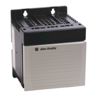
ControlLogix Redundant Power Supply
Catalog Numbers 1756-PA75R/A (85-265V AC Redundant Power Supply),
1756-PB75R/A (19-32V DC Redundant Power Supply)
Use this publication as a guide when installing the ControlLogix™ 1756-PA75R/A
and 1756-PB75R/A power supplies. These supplies may only be used with Series B
ControlLogix chassis.
To: See page:
See a Description of the Redundant Power Supply 6
See an Overview of the Installation Process 6
Prepare for Installation 6
Identify the Components of a Redundant Power Supply System 7
Recognize Redundant Power Supply Physical Features 8
Use System Set-up Recommendations 9
Allow Sufficient Mounting Space 10
Install Your Redundant Power Supply 11
Ground Your Redundant Power Supply 13
Connect the Cable to the Redundant Power Supply and the Chassis
Adapter Module
14
Connect Solid State Relay 15
Connect Power 16
Route Line Power and Cables 17
Remove the Protective Label 18
Activate the Redundant Power Supply System 18
See Input Power Requirements and Transformer Sizing 19
Troubleshoot with the Status Indicators 20
Replace a Redundant Power Supply 21
See 1756-PA75R/A and 1756-PB75R/A Specifications 22
Allen-Bradley HMIs

 Loading...