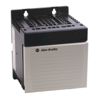
ControlLogix Redundant Power Supply 11
Publication 1756-IN573C-EN-P - October 2003
Install Your Redundant Power Supply
1. Use the mounting dimensions in Figure 6.
Figure 6
The 1756-PA75R/A and 1756-PB75R/A power supplies use the same
mounting dimensions as the 1756-A4 chassis.
2. Drill holes in the back panel of the enclosure for redundant power supply
mounting tabs.
Figure 7
ATTENTION
Do not drill holes for a redundant power supply above
installed equipment (e.g. chassis). Metal chips from drilling
can damage the backplane and cause intermittent operation.
42668
15.8cm
(6.22in)
7.0cm
(2.76in)
17.5cm
(6.88in)
1.1cm
diameter
(0.433in)
0.55cm
diameter
(0.217in)
0.55cm
diameter
(0.217in)
14.4cm
(5.66in)
1756-PA75R/A and
1756-PB75R/A power
supplies use the same
mounting dimensions as
the 1756-A4 chassis.
20288
Allen-Bradley HMIs

 Loading...