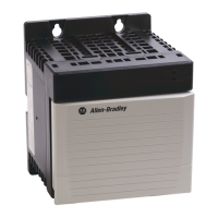
ControlLogix Redundant Power Supply 19
Publication 1756-IN573C-EN-P - October 2003
Input Power Requirements and Transformer Sizing
With the graphs in Figure 20, you can:
• Use the real power value in watts to determine the amount of heat
dissipation you will have inside the enclosure.
• User the appropriate power value in VA to estimate power
distribution sizing.
• Use the transformer load value in VA of each power supply plus all other
loads on a transformer to determine the required transformer size.
Use the graphs in Figure 20 to determine the input power requirements for the
supplies, given the power they are providing to the modules in the chassis. The
vertical axis of each graph shows the backplane power consumed by all of the
modules in the chassis; the horizontal axis shows input power requirements of the
power supply. To use the graphs:
1. Add all of the backplane power (i.e. watts) for all of the modules in
the chassis.
2. Find the number from step 1 on the vertical axis.
3. Follow that value to the right until it intersects the line on the graph.
4. Find the associated input power rating consumed by the power supply on
the horizontal axis.
For example, if the power consumption of all of the modules in the chassis is
30 watts, a 1756-PB75R consumed approximately 50 watts of Real Power.
Figure 20
Power factor circuitry reduces transformer sizing requirements.
apparent power (Watts)
transformer load (VA) = real power (Watts)
and
real power (Watts)
backplane
power load
(Watts)
real power (Watts)
backplane
power load
(Watts)
1756-PA75R/A (ac)
1756-PB75R/A (dc)
43588
43589
Allen-Bradley HMIs

 Loading...