8 ControlLogix Redundant Power Supply
Publication 1756-IN573C-EN-P - October 2003
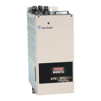
Recognize Redundant Power Supply Physical Features
Your redundant power supply has multiple physical features as shown below.
Figure 3
Table 2 Redundant Power Supply Physical Features
Physical Feature Description
Plastic barrier The barrier separates the input power cable from the annunciator cable.
Male cable connector The cable connector accommodates the female end of the 1756-CPR2 cable
and connects power to the chassis. For more information, see page 14.
Diagnostic status indicators There are two indicators:
• Power
• Non-Red (Nonredundancy)
For more information on the status indicators, see page 20.
ON/OFF switch Switch that turns the backplane power ON and OFF at the connected
chassis. (Up is the ON position.)
Solid state relay connections These contacts allow optional failure annunciation when wired to a
standard input module. The solid state relay contacts are normally open, but
held closed during normal operation. For more information on these
connections, see page 15.
Power input connections These connections allow you to wire input power to the redundant power
supply. For more information on these connections, see page 16.
42656
Diagnostic LEDs
ON/OFF switch
Solid state relay
connections
Male cable
connector
Supply shown
without door
or label.
Plastic barrier
Power input
connections

 Loading...