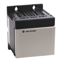
10 ControlLogix Redundant Power Supply
Publication 1756-IN573C-EN-P - October 2003
Allow Sufficient Mounting Space
Figure 5
For more information on spacing requirements between chassis, see the
ControlLogix Chassis Installation Instructions, publication number 1756-IN080.
IMPORTANT
Make sure you meet these minimum spacing requirements:
• 10.2cm (4in) between redundant power supplies and
cabinet housing the control system
• 2.55cm (1in) between redundant power supplies
• 15.3cm (6in) between chassis and heat source
• 5.1cm (2in) between wireway and top or bottom of chassis
• 5.1cm (2in) between wireway and power supply
42667
10.2cm
(4in)
2.55cm
(1in)
10.2cm
(4in)
15.3cm
(6in)
10.2cm
(4in)
5.1cm (2in)
5.1cm (2in)
Wireway
Table 3 lists the widths of each ControlLogix
chassis type with a Redundant Power Supply
Chassis Adapter module installed. Keep these
widths in mind when mounting your chassis.
Table 3 Width of Chassis with Redundant
Power Supply Chassis Adapter Module
Installed
Catalog
Number:
Total Width:
1756-A4 18.5cm (7.30in)
1756-A7 29.0cm (11.44in)
1756-A10 40.5cm (15.96in)
1756-A13 51.0cm (20.10in)
1756-A17 66.0cm (26.0in)
15.3cm
(6in)
15.3cm
(6in)
10.2cm
(4in)

 Loading...