6 ControlLogix Redundant Power Supply
Publication 1756-IN573C-EN-P - October 2003
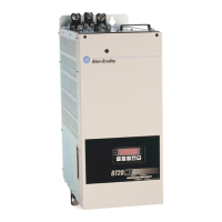
Description of the Redundant Power Supply
These supplies are part of a redundant power supply system that provides
additional uptime protection for a chassis used in critical applications. The two
remotely-mounted supplies are designed to share the current required by the
chassis. They are available in AC (1756-PA75R/A) and DC (1756-PB75R/A) versions
that can be mixed or matched when used in tandem.
In the event of a failure by one redundant power supply, the remaining supply will
accommodate the entire load of the chassis without disruption to chassis activity.
Overview of the Installation Process
Follow these steps when installing and powering your Redundant Power
Supply system.
1. Allow Sufficient Mounting Space
2. Install Your Redundant Power Supply
3. Ground Your Redundant Power Supply
4. Connect the Cable to the Redundant Power Supply and the Chassis Adapter
Module
5. Connect Solid State Relay
6. Connect Power
7. Activate the Redundant Power Supply System
The steps are described in detail, along with other important information,
throughout this installation instructions.
Prepare for Installation
You need the tools shown below to install a ControlLogix redundant power supply.
Figure 1
1/8” slotted screwdriver
1/4” slotted (#2) or
phillips screwdriver
torque screwdriver
needle-nose pliers
wire stripper
42654
electric drill

 Loading...