Rockwell Automation Publication 1769-IN028C-EN-P - August 2016 13
Compact I/O Expansion Power Supplies
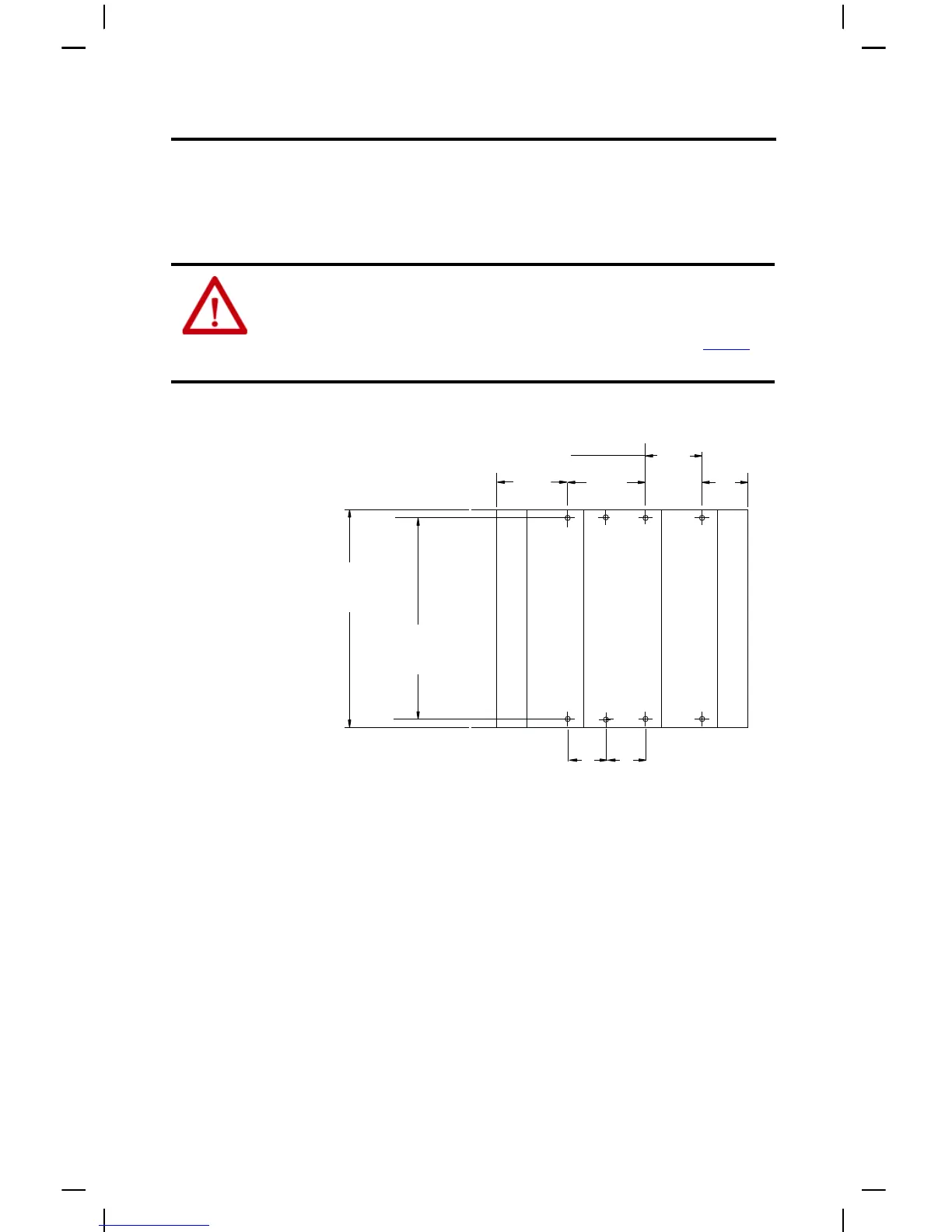
Mount the Panel
Mount the power supply to a panel by using four screws per module. Use M4 or #8 panhead
screws. Mounting screws are required on each power supply panel mounting tab.
Panel Mounting Using the Dimensional Template
Mount a Power Supply on a DIN Rail
The power supply can be mounted using the following DIN rails:
• 35 x 7.5 mm (EN 50 022 - 35 x 7.5)
• 35 x 15 mm (EN 50 022 - 35 x 15)
1. Before mounting a power supply or module on a DIN rail, close the DIN rail latches.
ATTENTION: This product is intended to be mounted to a well-grounded mounting surface such
as a metal panel. Additional grounding connections from the power supply's mounting tabs or
DIN rail (if used) are not required unless the mounting surface cannot be grounded. Refer to
Industrial Automation Wiring and Grounding Guidelines, Allen-Bradley publication 1770-4.1
, for
additional information.
Compact I/O
Compact I/O
End Cap
End Cap
Power Supply
For more than 2 modules: (number of modules -1) X 35 mm (1.38 in.)
132
(5.197)
40
(1.58)
70
(2.76)
28.5
(1.12)
35
(1.58)
35
(1.58)
122.6 ±0.2
(4.826 ±0.008)
All dimensions are in mm (in.). Hole spacing tolerance: ±0.4 mm (0.016 in.)
 Loading...