Rockwell Automation Publication 1769-IN028C-EN-P - August 2016 23
Compact I/O Expansion Power Supplies
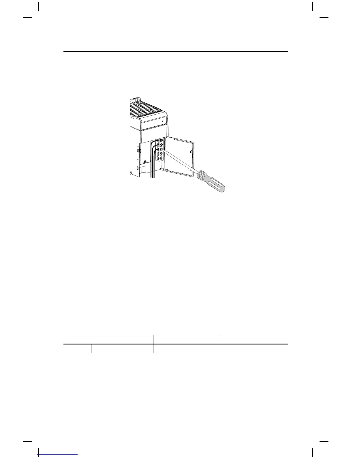
Wire the Fingersafe Terminal Block
When wiring the terminal block, keep the fingersafe cover in place.
1. Loosen the terminal screws to be wired.
2. Route the wire under the terminal pressure plate.
You can use the bare wire or a spade lug. The terminals accept a 6.35 mm (0.25 in.) spade
lug.
3. Tighten the terminal screw, making sure that the pressure plate secures the wire.
Recommended torque when you tighetn terminal screws is 1.27 N•m (11.24 lb•in).
Wire Size and Terminal Screw Torque
Each terminal accepts as many as two wires with the following restrictions.
TIP The terminal screws are non-captive. Therefore, it is possible to use a ring lug [maximum 1/4-
inch o.d. with a 0.139-inch minimum i.d. (M3.5)] with the module.
TIP If you must remove the fingersafe cover, insert a screwdriver into one of the square wiring
holes and gently pry the cover off. If you wire the terminal block with the fingersafe cover
removed, you cannot put it back on the terminal block because the wires are in the way.
Wire Type Wire Size Terminal Screw Torque
Solid Cu-90 °C (194 °F) 2.5 mm
2
(14 AWG) 1.27 N•m (11.24 lb•in)
 Loading...