26 Rockwell Automation Publication 22C-UM001J-EN-E - January 2017
Chapter 1 Installation/Wiring
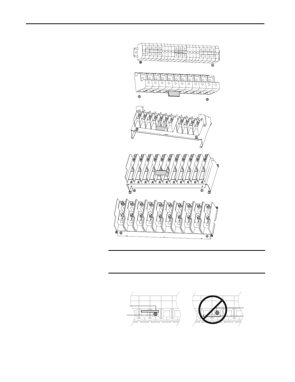
Figure 9 - Power Terminal Blocks (Frames E through H)
IMPORTANT For Frame E, 240V 30...37 kW (40...50 HP) and 480V 55...75 kW (75...100 HP)
drives, take care to place the wire beneath the jumper and not above it when
connecting to terminals P1 and P2.
R/L1
S/L2
T/L3
P1
P2
DC–
U/T1
V/T2
W/T3
Frame E:
240V 480V
30-37 kW 55-75 kW
(40-50 HP) (75-100 HP)
Frame F
R/L1
S/L2
T/L3
P1
P2
DC–
U/T1
V/T2
W/T3
Frame G
R/L1
S/L2
T/L3
P1
P2
DC–
U/T1
V/T2
W/T3
Frame H
R/L1
S/L2
T/L3
DC–
DC+
U/T1
V/T2
W/T3
Frame E:
480V
37-45 kW
(50-60 HP)
R/L1
S/L2
T/L3
P1
P2
DC–
U/T1
V/T2
W/T3
See note at the bottom
of this page.
P1 P2 DC- P1 P2 DC-
Bottom view of terminal block and wire
Jumper
Wire
Wire
Jumper
Correct Incorrect
 Loading...