Rockwell Automation Publication 2711P-UM006E-EN-P - January 2017 127
Install and Replace Components Chapter 5
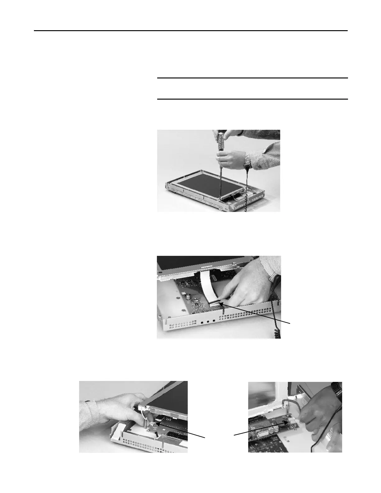
Follow these steps to replace the backlight.
1. Disconnect power from the terminal.
2. Remove the display module bezel.
3. Remove the four screws that secure the LCD display.
For 700 displays, remove the four screws that secure the display bracket.
4. Lift the LCD display and detach the display connector from the circuit
board.
The circuit board layout can vary for each terminal model. The location of
the connector varies by model.
5. Detach the backlight connectors from the circuit board.
• The 1250 has one or two backlight connectors depending on the series
of the display.
• The 1500 has four backlight connectors.
The 700 series C display is not secured by screws and is retained only by
a bracket. Use care not to drop the display once the bezel is removed.
Backlight
Connector
1250
1500
 Loading...