5
Bulletin 700S-CF
Safety Control Relays
Specifications
General
➊ For sixteen or more strands, end ferrule is required.
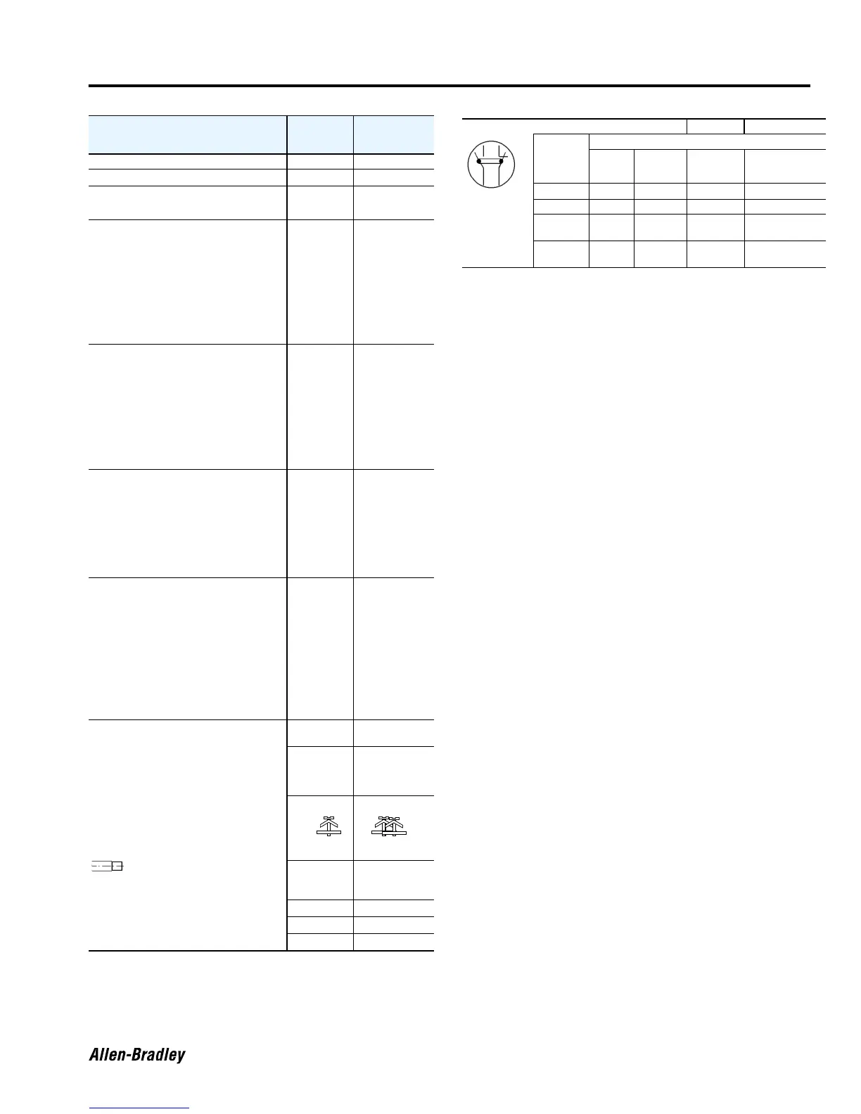
➋ Defined in IEC 947-5-1 annex L. Mechanically-linked is a relationship
between contacts of opposite types (i.e., N.O. and N.C.).
➌ If the accessory is a pneumatic timer or latch, there is no
mechanically-linked guidance; the accessory contacts are
independent.
Cat. No.
700S-CF
main poles
front auxiliary
contacts
Contact Ratings — NEMA A600, P600 A600, Q600
UL General Purpose Current
20A
!0A
Minimum Contact Rating
17 – 19.9V 30 mA
20 – 24V 20 mA
Contact Ratings — IEC
AC-15 (solenoids,
contactors) at rated
voltage
IEC 947, EN 60947
24V 15 A 6 A
48V 15 A 6 A
120V 14 A 6 A
240V 10 A 5 A
400/415V 5 A 3 A
480V/500V 2.5 A 1.6 A
600V 1.8 A 1.2 A
690V 1 A 1.0 A
AC-12
(Control of
AC resistive
loads)
IEC 947, EN
60947
40°C
I
th
20 A 10 A
230V 10 kW
400V 17 kW
690V 30 kW
60°C
I
th
20 A 6 A
230V 8 kW
400V 14 kW
690V 24 kW
DC-12
(Control of DC resistive
loads)
IEC 947
EN 60947
24V 12 A 12 A
48V 9 A 9 A
60V 5.0 A 3.5 A
110V 3.5 A 3.5 A
125V 3.0 A 3.0 A
220V 0.55 A 0.55 A
440V 0.2 A 0.2 A
DC-13 IEC 947,
EN 60947,
Solenoids and
contactors 24V 5 A 5 A
48V 2 A 2 A
60V 1.5 A 1.5 A
125V 0.7 A 0.55 A
220V 0.25 A 0.25 A
440V 0.12 A 0.12 A
600V 0.1 A 0.1 A
Avg-Mechanical Life
(ops)
[Mil] 15 15
Average-
Electrical
Life
(ops)
AC-15
(240V, 3 A)
[Mil] 1.1 0.75
Terminal Cross-Sections
Terminal Type
Terminal Size per IEC 947-1 2 x A4 2 x A4
Solid/
Stranded
➊
1 or 2
Conductor
Conductor
[mm
2
]
[mm
2
]
1.5
…
6
1
…
4
0.5
…
2.5
0.75
…
2.5
Max. Wire Size per UL/CSA [AWG]
16
…
10 18
…
14
Tightening Torque [lb.-in.]
8.9
…
22 8.9
…
13.3
Tightening Torque [N•m]
1
…
2.5 1
…
1.5
Yes Yes
Location of
welded
N.O.
contacts
State of N.C. Contacts if N.O. contact welds
Main Front aux.
Left side
aux.
Right side aux.
Main Open Open ➌ Open Open
Front aux. Open Open ➌ Open Open
Left side
aux.
Open Open ➌ Open Open
Right side
aux.
Open Open ➌ Open Open
Mechanically
-linked
Contacts ➋

 Loading...


