8 Rockwell Automation Publication 193-IN080A-EN-P - September 2018
E300 Electronic Overload Relay
For the E300 Electronic Overload Relay to function properly and protect your motor, it needs a control voltage (24V DC, 120V AC,
240VAC).Connect the control voltage to the device by attaching wires to the A1 (positive) and A2 (negative) terminals, which are located on the
bottom of the control module of the E300 relay. Figure 4 shows this configuration.
Figure 4 - Control Module Wiring
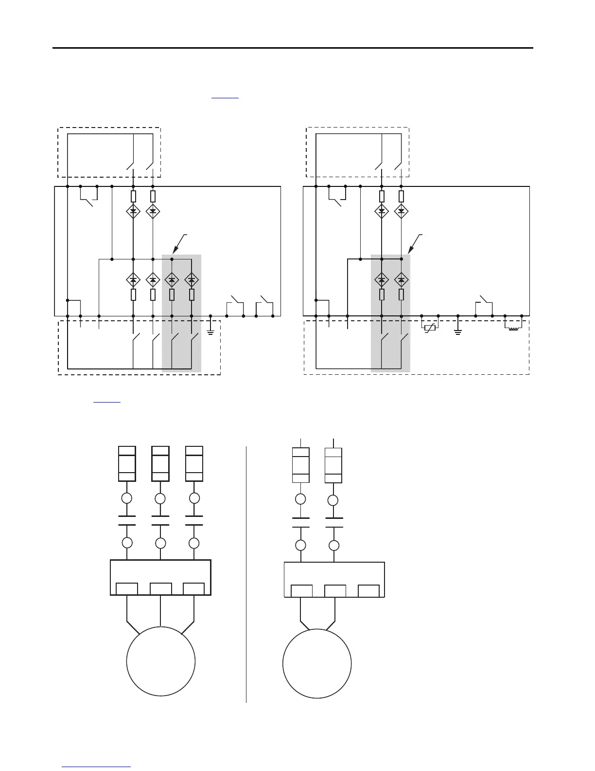
The E300 relay typically is wired in one of two different motor connections: a three-phase, direct-on-line (DOL), and a single-phase, full-voltage
connection. Figure 5 shows these connections.
Figure 5 - E300 Relay DOL and Single-phase Full-voltage Connections (NEMA Nomenclature)
193-EIO…
193-EIOGP…
A1
Relay 0
IN1IN0A2R04R03
Additional Inputs for 193-EIO-63…
A1
Relay 0
IN1IN0A2R04R03
Additional Inputs for 193-EIOGP-63…
A1 A1 A2
Relay 1 Relay 2
(+) (-)
A1 A1
A2
(+) (-)
Relay 1
Ground
Fault
IN4IN3IN2 R13PEIN5 R24R23R14
IN3IN2 PE
+t°
IT2IT1
PTC
R13 S2S1R14
Three-phase Direct-on-Line
Single-phase Full Voltage
Short-circuit
Protection Device
Short-circuit
Protection Device
L1 L2 L3
E300 Relay E300 Relay
Motor Motor
2/T1 4/T2 6/T3
2/T1 4/T2 6/T3
T1
T2
T3
T1 T2
L1 L2

 Loading...


