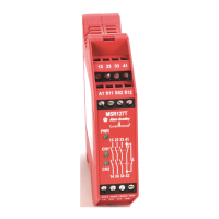
Installation Instructions
Original Instructions
MSR127 Minotaur Monitoring Safety Relays
Catalog Number 440R-N23124, 440R-N23125, 440R-N23126, 440R-N23127, 440R-N23128, 440R-N23129, 440R-N23129M, 440R-N23130,
440RN23131, 440R-N23132, 440R-N23132S, 440R-N23133, 440R-N23134, 440R-N23135, 440R-N23135M, 440R-N23135S, 440R-N23213
Summary of Changes
This publication contains the following new or updated information. This list
includes substantive updates only and is not intended to reflect all changes.
Translated versions are not always available for each revision.
Safety
This device is intended to be part of the safety-related control system of a
machine.
Safety Notes
Before installation, a risk assessment must be performed to determine whether
the specifications of this device are suitable for all foreseeable operational and
environmental characteristics of the machine to which it is to be fitted. At regular
intervals during the life of the machine, check whether the characteristics
foreseen remain valid.
Rockwell Automation cannot accept responsibility for failure of this device if the
procedures given in these instructions are not followed or if it is used outside the
recommended specifications in these instructions.
Repair
If there is any malfunction or damage, do not attempt to repair. The unit must be
replaced before machine operation is allowed.
Declaration of Conformity
Rockwell Automation declares that all MSR127 safety relays are in
conformity with Directives 2014/30/EU, 2006/42/EC, 2011/65/EU as
specified in the Declaration of Conformity available from
rok.auto/certifications
.
Functional Description
The unit is enabled once supply is powered up and the safety circuits are closed.
The PWR status indicator is on.
A valid reset operation activates the safety outputs. The CH1 and CH2 status
indicators of the output are lit. At demand of the safety function and if any fault,
the safety outputs are de-energized within the specified response time.
Fault Detection
If a fault occurs, the internal relay circuit forces the safety outputs off. One or both
output status indicators may be off. The PWR indicator may be flashing. Remove
the fault and cycle the safety input to re-enable the device. Cycling power to the
safety relay can also clear the fault condition.
Diagnostics
Auxiliary (N.C.) outputs 41…42 monitor the safety output state.
Topic Page
Summary of Changes 1
Safety 1
Declaration of Conformity 1
Functional Description 1
Diagnostics 1
Safety Input 2
Reset 2
Wiring Examples 2
Circuit Diagram 2
Approximate Dimensions 3
Installation 3
Safety Specification 3
Technical Specifications 3
Topic Page
Updated title of publication 1
Updated Declaration of Conformity section 1
Updated Positive Edge section 2
Updated Circuit Diagram section 2
Updated Safety Specification section 3
ATTENTION: Danger of serious injuries.
Misuse can result in malfunction.
• Only authorized and trained personnel must start up,
assemble, install, manipulate, or retrofit the device.
• Installation must be in accordance with these instructions.
• Do not defeat, tamper, remove, or bypass this unit.
IMPORTANT
The safety inputs of these products are described as
normally closed (N.C.), that is, with the guard closed,
actuator in place (where relevant) and the machine able to
be started. Exposure to shock and/or vibration in excess
of what is stated in IEC 60068 part: 2-6/7 must be avoided.
Adherence to the recommended inspection and
maintenance instructions forms part of the warranty.
ATTENTION: MSR127 safety relays are not repairable.

 Loading...