Publication 2711P-UM001A-EN-P
5-4 Installing and Replacing Components
To replace the Logic Module:
Before replacing the Logic Module, you must remove the
Communication Module (if attached). You will also need to remove
the Internal RAM and Compact Flash from the Logic Module to reuse
in the new Logic Module.
1. Disconnect power from the terminal.
2. Disconnect all power and communication cables.
3. If Display Module is removed from panel, set the module,
display side down, on a clean, flat, stable surface to prevent
scratches.
4. Remove the 4 screws that attach the Communication Module (if
attached) to the Logic Module. Carefully lift the Communication
Module away from the Logic Module.
5. Remove the 6 captive screws that secure the Logic Module to the
Display Module.
6. Carefully lift the Logic Module away from the back of the
Display Module.
7. Remove the internal RAM and Compact Flash from the Logic
Module if you want to reuse them in the future. Refer to page
5-2.
8. Install the new Logic Module as described on page 5-3.
9. Attach the Communication Module (if necessary).
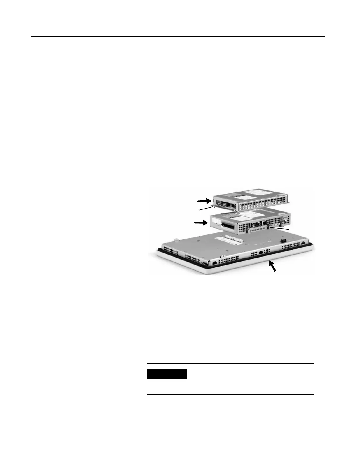
Logic Module
Communication Module
Display Module
Captive Screw
Screw
IMPORTANT
Wear a properly ground ESD wristband
before touching any of the electronic
components in the Logic Module.

 Loading...