Publication 2711P-UM001A-EN-P
5-6 Installing and Replacing Components
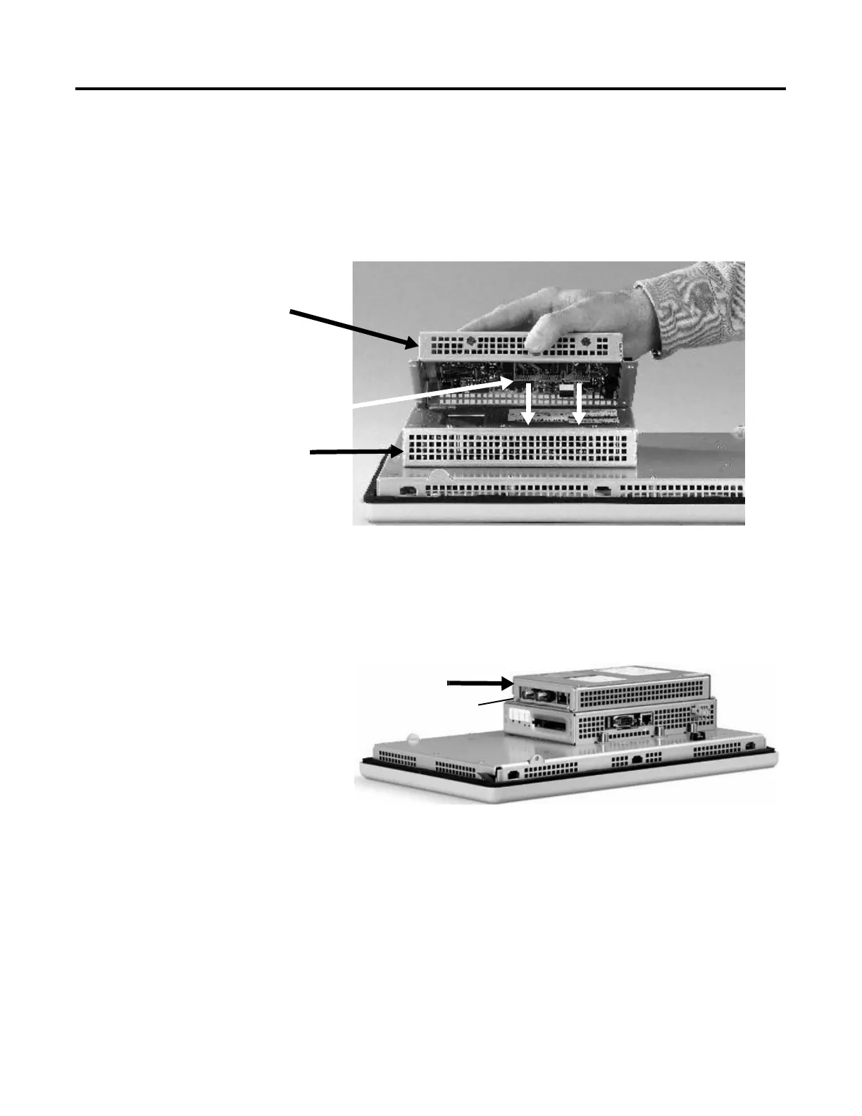
4. Position the Communication Module over the Logic Module so
that the connectors on bottom of module align with connectors
on Logic Module.
5. To prevent Electrostatic Discharge (ESD) between the modules,
allow the Communication Module to touch the Logic Module
before making connection.
6. Push down on Communication Module until connectors are
firmly seated.
7. Tighten the 4 screws that secure the Communication Module to
the Logic Module. Tighten screws to a torque of .68 N•m (6-8
in-lb).
To replace a Communication Module:
1. Disconnect power from the terminal.
2. Disconnect communication cables from the Communication
Module.
3. Remove the 4 screws that secure the Communication Module to
the Logic Module.
4. Carefully lift the Communication Module away from the Logic
Module and set aside.
5. Follow steps 4 - 7 above.
Communication
Module
Connector
Logic Module
Screw
Attached
Communication Module

 Loading...