Publication 2711P-UM001A-EN-P
Installing and Replacing Components 5-15
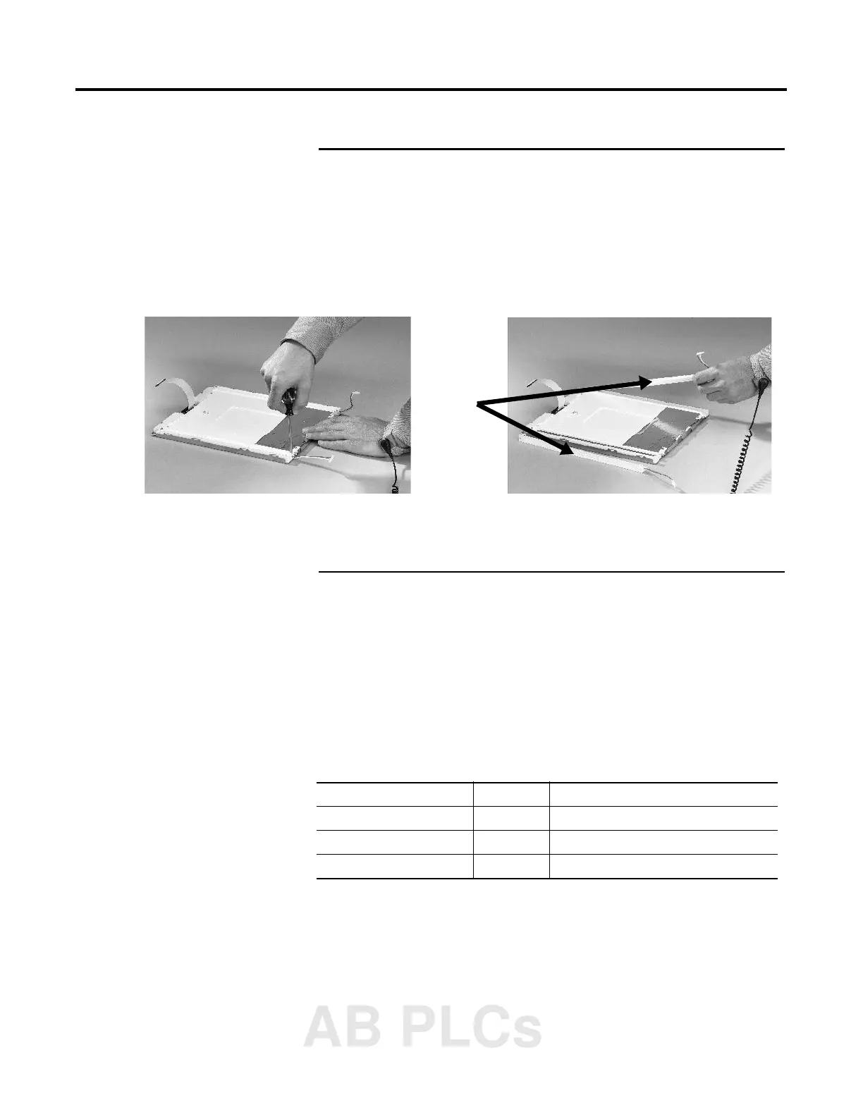
For PanelView Plus 1250 (has 2 Backlights)
Work on a clean, flat, stable surface to protect the display from
debris, scratches and damage.
8. Remove the 2 screws that secure each of the two backlights and
then remove the backlights.
9. Insert the new backlights and then secure each with the 2
screws.
10. Attach the Backlight Connector to the circuit board (shown in
step 5 on page 5-14).
11. Attach the LCD Display Connector to the circuit board (shown in
step 4 on page 5-13).
12. Secure the LCD Display by attaching the 4 screws. The terminals
use different size screws. Use the following chart to tighten the
screws.
13. Replace the Display Module bezel as described on 5-12.
Backlights
PanelView Plus Screw Size Torque
700 2.5 mm .68 N•m (6-8 in-lb)
1000/1250 #4 .68 N•m (6-8 in-lb)
1500 #6 .90 - 1.1 N•m (8-10 in-lb)
AB PLCs

 Loading...