Publication 1760-GR001C-EN-P - April 2005
Pico Controller 1-13
Cursor Display
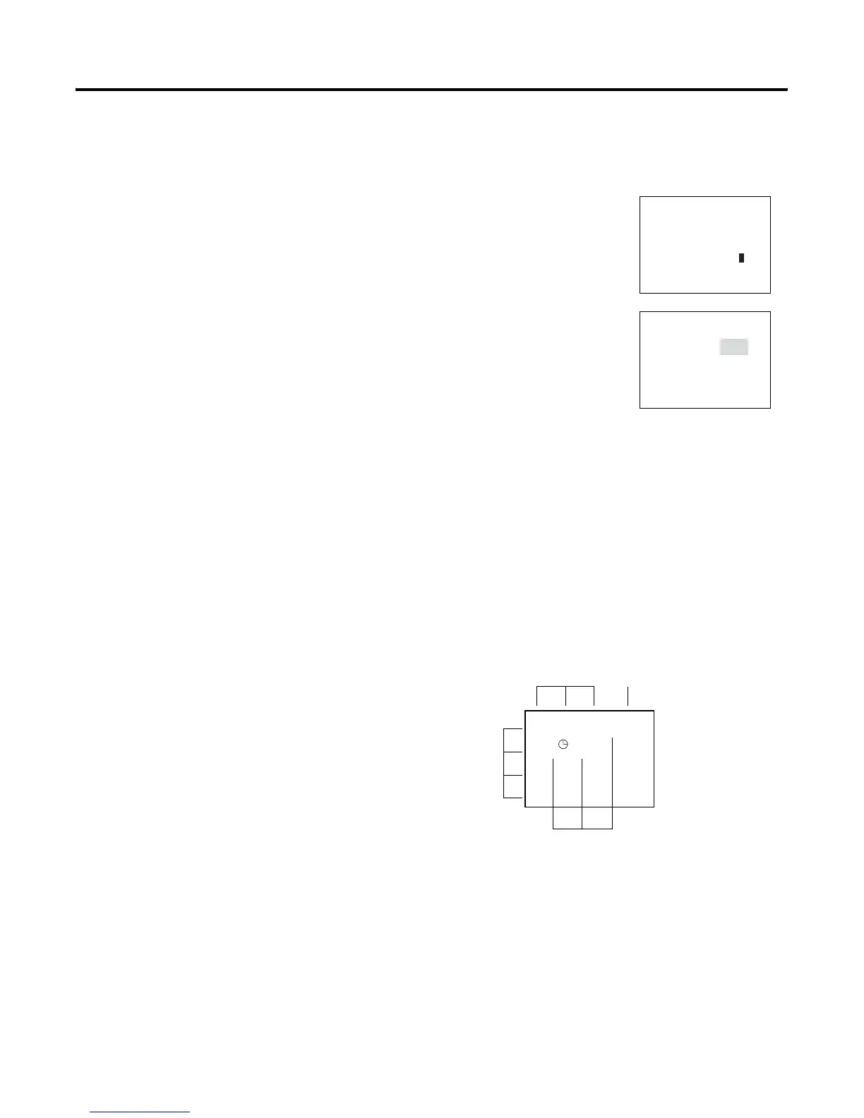
Circuit Diagram Menu
Each rung can hold four instructions, three input instructions
(contacts) and one output instruction (coil or relay). Rungs are
connected together through branches at the three positions between
instructions. All programming of Pico can be done using the display
and keypad.
WINTER TIME
DAY : MO
TIME :
01 25
WINTER TIME
DAY :
MO
TIME : 01:25
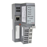
There are two different cursor types:
Full block navigation is shown as a flashing
block:
• Move cursor with the left/right arrows
• When in circuit diagram, also use
up/down arrows
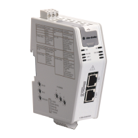
Parameter change cursor flashes the selected
parameter:
• Change position with left/right arrows
• Change values with up/down arrows
Flashing values/menus are highlighted in grey
in this manual.
I1 -I2 -T1 -{Q1
I2 -
1
Input
Contacts
Output
Coil Field
Circuit
Connections/Rungs
Branch Connections
 Loading...