Do you have a question about the Allen-Bradley 1788-EN2DNR and is the answer not in the manual?
Lists documents and resources for related Rockwell Automation products.
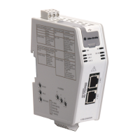
Introduces the EtherNet/IP-to-DeviceNet linking device and its two designs.
Details the features of both the 1788-EN2DNR and 1788-EN2DNROM linking devices.
Instructions on how to mount the 1788-EN2DNR linking device on a DIN rail.
Instructions on how to mount the 1788-EN2DNROM linking device to a panel.
Explains DeviceNet safety messages and CIP safety connections.
Describes the OSCAR feature for dynamic scanlist configuration.
Guidelines for environmental conditions and enclosure requirements for the device.
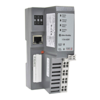
Lists the certifications held by the 1788-EN2DNROM linking device.
Details the technical specifications, including operating temperatures and power requirements.
Lists the required hardware and software for installing and using the linking device.
Instructions for connecting the device to an EtherNet/IP network via RJ45 ports.
Steps for connecting the device to the DeviceNet network using a mini-style connector.
Methods for setting DeviceNet node address and baud rate using switches or software.
Overview of methods to set the linking device's IP address.
Guide to setting the IP address using the device's rotary switches.
Steps for configuring the IP address using a DHCP or BOOTP server.
Flowchart illustrating the IP address configuration process upon power-up.
Instructions for setting the IP address using RSLinx software.
Guide to configuring the IP address via the device's web interface.
Explains the authentication process when accessing the linking device's web pages.
Steps to configure the RSLinx driver for the linking device.
Instructions on how to register the EDS file in RSLinx software.
Guidelines for environmental conditions and enclosure requirements for the device.
Details ATEX Zone 2 approval and related safety requirements.
Explains Class I Division 2 Group A,B,C,D approval and safety warnings.
Lists the certifications for the 1788-EN2DNR linking device.
Details technical specifications for the 1788-EN2DNR linking device.
Lists required hardware and software for the 1788-EN2DNR linking device.
Instructions for connecting the 1788-EN2DNR to an EtherNet/IP network via RJ45 ports.
Steps for connecting the 1788-EN2DNR to the DeviceNet network.
Methods for setting DeviceNet node address and baud rate using switches or software.
Overview of methods to set the linking device's IP address.
Guide to setting the IP address using the device's rotary switches.
Steps for configuring the IP address using a DHCP or BOOTP server.
Flowchart illustrating the IP address configuration process upon power-up.
Instructions for setting the IP address using RSLinx software.
Guide to configuring the IP address via the device's web interface.
Explains the authentication process when accessing the linking device's web pages.
Steps to configure the RSLinx driver for the linking device.
Instructions on how to register the EDS file in RSLinx software.
Steps to use RSNetWorx for DeviceNet software for configuration.
How to set DeviceNet node address and baud rate using RSNetWorx.
Procedure to enable or disable the Autobaud feature using RSNetWorx.
Steps to configure DeviceNet I/O using RSNetWorx for DeviceNet software.
Explains the importance of I/O table organization and size restrictions.
Explains how to work with the linking device in the Studio 5000 environment.
Steps to create a new project and add the linking device to Studio 5000.
Explains the input, output, and status assembly objects and their mapping.
Details the status assembly format and fields for diagnostic information.
Instructions for connecting the linking device to a workstation via USB.
Steps to configure the USB driver for RSLinx software.
Procedures for installing or removing the SD card, including safety warnings.
Using RSLogix 5000 to load or store the linking device configuration to an SD card.
Steps to store the current linking device configuration to the SD card.
Steps to load configuration from the SD card to the linking device.
Instructions on how to access the device's diagnostic web pages.
Explains the DeviceNet-specific diagnostic pages.
Information on identifying active DeviceNet nodes on the network.
Information on identifying DeviceNet nodes in an idle state.
Information on identifying DeviceNet nodes that are in a faulted state.
Information on identifying DeviceNet nodes with incorrect device types.
Displays current status of DeviceNet nodes and meanings of status codes.
Explains the Ethernet-specific diagnostic pages.
Provides general Ethernet information for the linking device.
Displays Ethernet network address information and status for ports.
Information on current Ethernet settings and packet statistics.
Information about the network topology and specific ring information.
Explains miscellaneous sections of the diagnostic web pages.
Hexadecimal dump of the fatal event log for diagnostic purposes.
Information provided for support issues.
Explains the meaning of status LEDs for the linking device module.
Explains the status indicators for the EtherNet/IP network interface.
Explains the status indicators for the DeviceNet network interface.
Information on contacting support for installation issues.
Procedures for returning products that are not functioning.
How to provide comments to improve the documentation.
| Operating Voltage | 24V DC |
|---|---|
| Enclosure | IP20 |
| Protocol | EtherNet/IP |
| Network Interface | RJ45 |
| DH+ Baud Rates | Not Applicable |
| Power Supply | External |
| Operating Temperature | 0 to 60 °C |
| Relative Humidity | 5% to 95% (non-condensing) |
| Certifications | CE, UL, C-UL |
| Ethernet Ports | 1 (10/100 Mbps) |