54 Rockwell Automation Publication 1788-UM059B-EN-P - September 2015
Chapter 4 Configure the Linking Device
Studio 5000 Environment
These procedures explain how to work with the linking device in the
Studio 5000® environment.
Add the Linking Device to a Studio 5000 Logix Designer Application
1. In the Studio 5000 Logix Designer® application, from the File menu,
choose New to create a new project.
The New Controller dialog box appears.
2. From the Type pull-down menu, choose the controller type.
3. From the Revision pull-down menu, choose the controller version.
4. In the Name box, type a name for the controller project.
5. Click OK.
A project is created.
Configure the Linking Device
1. In the left pane, right-click I/O Configuration.
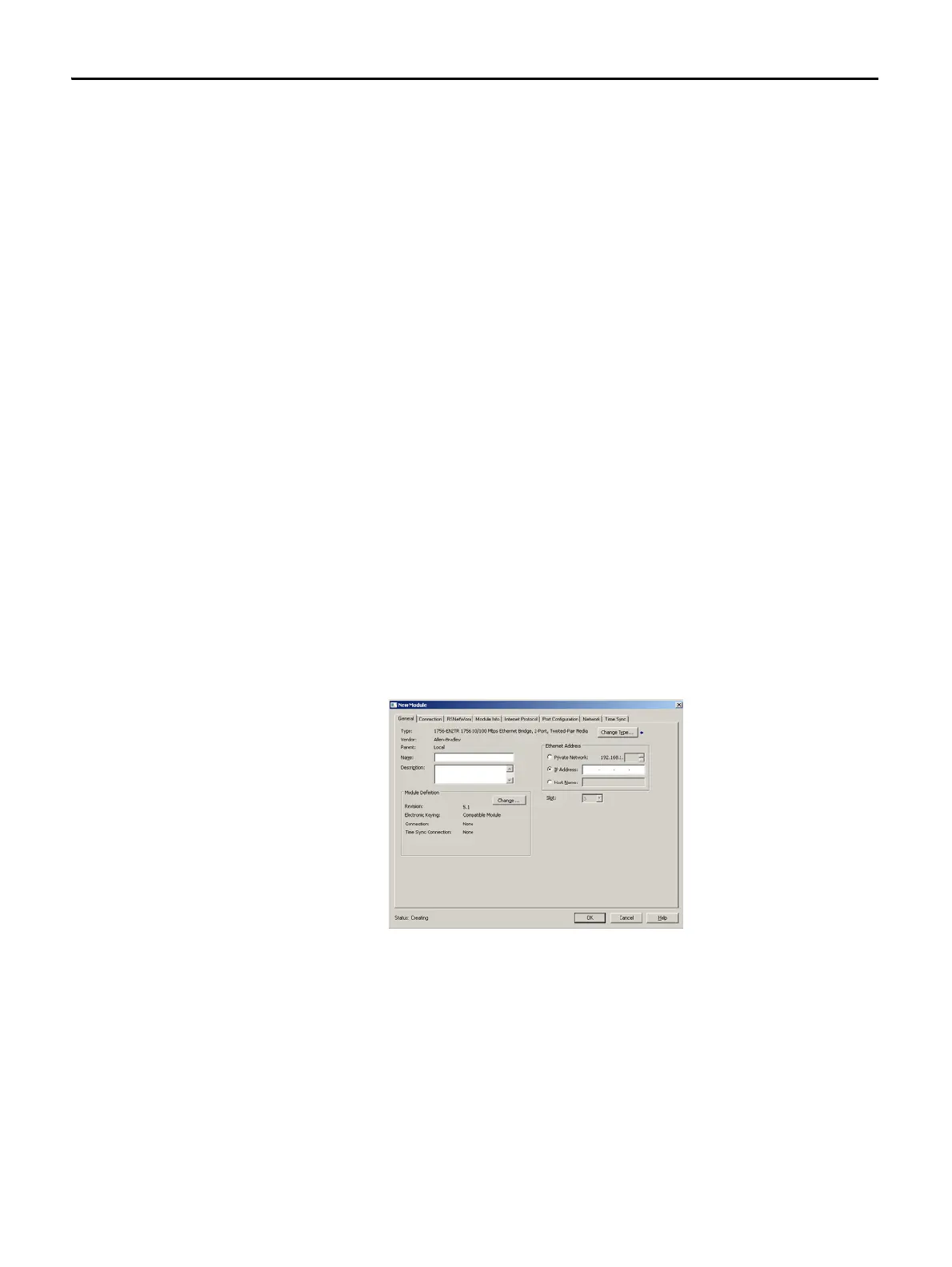
2. Click New Module.
3. From the Select Module Type dialog box, select any EtherNet/IP bridge
module (such as the 1756-EN2TR module) and click Create.
The New Module dialog box appears.
4. In the Slot Number pull-down, choose the slot number in which the device
resides.
5. Click OK.
6. In the right pane, right-click the EtherNet/IP module you just added to
your project and choose New Module.
 Loading...