Rockwell Automation Publication 1788-UM059B-EN-P - September 2015 35
Install the 1788-EN2DNR Linking Device Chapter 3
Connect the 1788-EN2DNR
Linking Device to the
DeviceNet Network
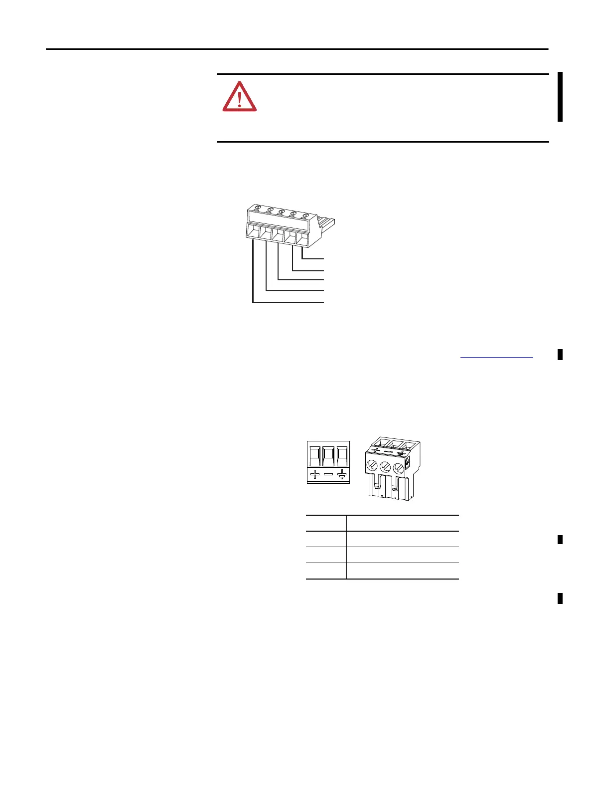
4. With power to the linking device off, connect the DeviceNet network
cable to the DeviceNet connector on the linking device.
The female terminal block connector is provided with the linking device.
5. Connect the power cable to the linking device.
The female terminal block connector is provided with the linking device.
6. Apply power to the linking device and DeviceNet network.
ATTENTION:
Power to this equipment must be supplied from a source compliant with the following:
• Class 2 approved to UL1310
• Limited Voltage Limited Current Supply compliant with UL508
• SELV source approved to IEC60950-1, IEC61010-2-201 or IEC62368-1 (ES1)
• PELV source approved to IEC60950-1, IEC61010-2-201 or IEC62368-1 (xyz)
If multiple power sources are used, do not exceed the specified isolation voltage.
The two 121 Ω termination resistors that come with the linking device are
required for proper network termination at each end of the trunk line. See the
DeviceNet Specification (available from ODVA, Inc at http://www.odva.org
) for
specific rules on DeviceNet connections and termination.
Pin No. Description
1 +24V DC
2GND
3PE (Protective Earth)
(Red) Net Power 24V DC
(White) CAN High +
CAN Shield
(Blue) CAN Low
(Black) Net Power 24V DC Common
 Loading...