18 Rockwell Automation Publication 1788-UM059B-EN-P - September 2015
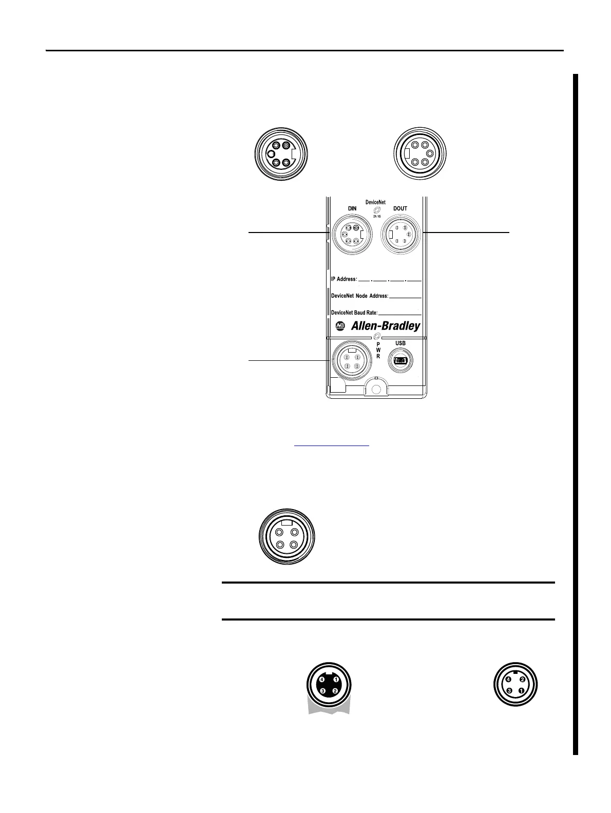
Chapter 2 Install the 1788-EN2DNROM Linking Device
Connect the
1788-EN2DNROM Linking
Device to the DeviceNet
Network
1. With power to the linking device off, connect the DeviceNet network
cable to the mini-style DeviceNet connector on the linking device.
2. Connect the mini-style power cable to the linking device.
3. Apply power to the linking device and DeviceNet network.
See the DeviceNet Specification (available from ODVA, Inc at
http://www.odva.org
) for specific rules on DeviceNet connections and
termination.
On Machine end devices, such as the 1788-EN2DNROM, use the EN-50044 wiring standard while
On-Machine cordsets with flying leads use the SAE-J-1738A standard for wiring. Use care to
follow the pin numbering convention shown below before powering up the unit.
1
4
2
5
3
1
4
3
2
5
Pin 1 Bare (Shield)
Pin 2 Red (+ Voltage)
Pin 3 Black (- Voltage)
Pin 4 White (CAN_H)
Pin 5 Blue (CAN_L)
Male 7/8 in. (22 mm)
Female 7/8 in. (22 mm)
Pin 1 Bare (Shield)
Pin 2 Red (+ Voltage)
Pin 3 Black (- Voltage)
Pin 4 White (CAN_H)
Pin 5 Blue (CAN_L)
Mini-style Auxiliary
Power In
DeviceNet 7/8 in. (22 mm)
Connector (Male)
DeviceNet 7/8 in. (22 mm)
Connector (Female)
Pin 1 NC (Not connected)
Pin 2 V+ (Input +24V DC)
Pin 3 V- (Input Power Common)
Pin 4 NC (Not connected)
2
1
4
3
1: NC (Black)
2: V- (White)
3: NC (Red)
4: V+ (Green)
1: NC (Red)
2: V+ (Green)
3: V- (White)
4: NC (Black)
Cordsets with Flying Leads (per SAE-J-1738A)
1788-EN2DNROM (per EN50044)
 Loading...