Rockwell Automation Publication 1788-UM059B-EN-P - September 2015 53
Configure the Linking Device Chapter 4
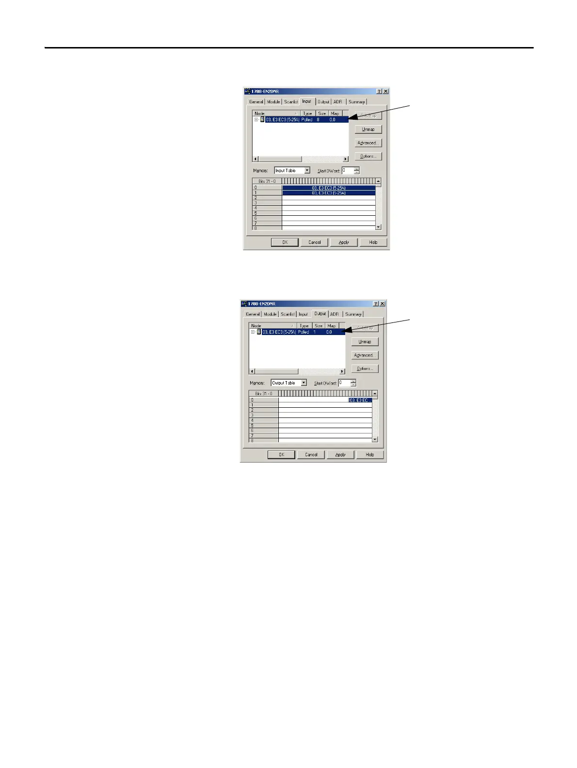
The Input mapping dialog box appears.
10. Click the Output tab.
The Output mapping dialog box appears.
11. Click Apply, and click Yes to download the scan list to the linking device.
12. Click OK.
The linking device starts scanning as soon as it finds entries in its scan list.
However, in Idle mode, output data is not sent to the devices.
The top portion of this dialog box lists the
devices in the scan list from which the linking
device receives input data. The bottom shows
the location in the Input table where the data
is placed for each device. This shows the
format of the Input table of the linking
device. This is the format of the input data
that is sent to the EtherNet/IP scanner.
The top portion of this dialog box lists the
devices in the scan list from which the linking
device sends output data. The bottom shows
the location in the Output table where the
data is placed for each device. This shows the
format of the Output table of the linking
device. This is the format of the output data
that is sent to the linking device from the
EtherNet/IP scanner.
 Loading...