EasyManuals Logo
Home>Allen-Bradley>Network Hardware>PicoTM Controller 1760

Allen-Bradley PicoTM Controller 1760 User Manual

Allen-Bradley PicoTM Controller 1760
66 pages
To Next Page IconTo Next Page
To Previous Page IconTo Previous Page
Page #38 background imageLoading...
Page #38 background image
Publication 1760-GR001C-EN-P - April 2005
2-12 Drawing a Circuit with Pico
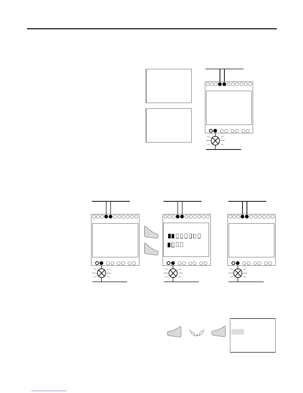
Operate Switch “S1” and “S2”
Return to Status Display with ESC
I1-I2----{Q1
I1-I2----{Q1
I1-I2----{Q1
“S1” on
“S2” on
Relay “Q1” picks up
I1-I2----{Q1
I
12 3 4 5 6 7
8
MO
13:34
Q1234
STOP
12............
RE I P
MO 02:00 ST
1.........RUN
PROGRAM...
RUN
PARAMETER
SET CLOCK..
Esc
Esc
Ok
Ok
or
12-I/O Pico 18-I/O Pico
In the next example, a timing relay will be added to the circuit.
Status display is activated.
Choose STOP mode.

Questions and Answers:

Question and Answer IconNeed help?

Do you have a question about the Allen-Bradley PicoTM Controller 1760 and is the answer not in the manual?

Allen-Bradley PicoTM Controller 1760 Specifications

General IconGeneral
BrandAllen-Bradley
ModelPicoTM Controller 1760
CategoryNetwork Hardware
LanguageEnglish

Related product manuals