Rockwell Automation Publication 750-IN001O-EN-P - October 2014 49
Lift and Mount the Drive Chapter 3
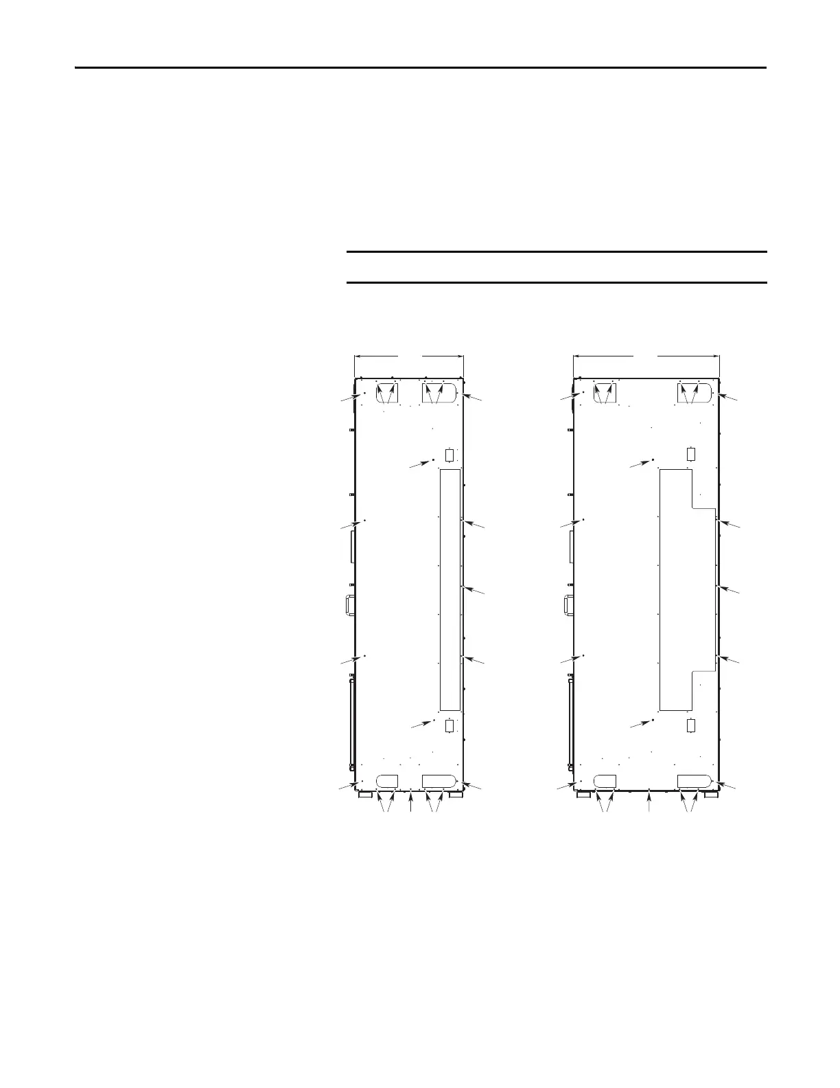
Join the Cabinets
12. Pass the M8 x 16 mm hex-head thread-forming screws from inside the
wiring bay through the clearance holes and start to engage the screws with
the holes in the cabinet options bay.
Make sure the cabinets are level and aligned and pushed tightly together.
13. Lightly tighten the screws in a uniform pattern.
Torque screws labeled ➊ to 11.3 N•m (100 lb•in).
Torque screws labeled ➋ to 9.0 N•m (80 lb•in).
Do not use hardware to draw cabinets together.
➊
➊
➊
➊
➊
➊
➊
➊
➊
➊
➊
600
(23.6)
800
(31.5)
➋
➋
➋
➋
➋
➋
➋
➊
➊
➊➊ ➊
➊ ➊ ➊ ➊ ➊ ➊
➊
➊
➊➊
 Loading...


