Rockwell Automation Publication 750-IN105D-EN-P - June 2018 27
PowerFlex 750-Series Service Cart and DC Precharge Module Lift
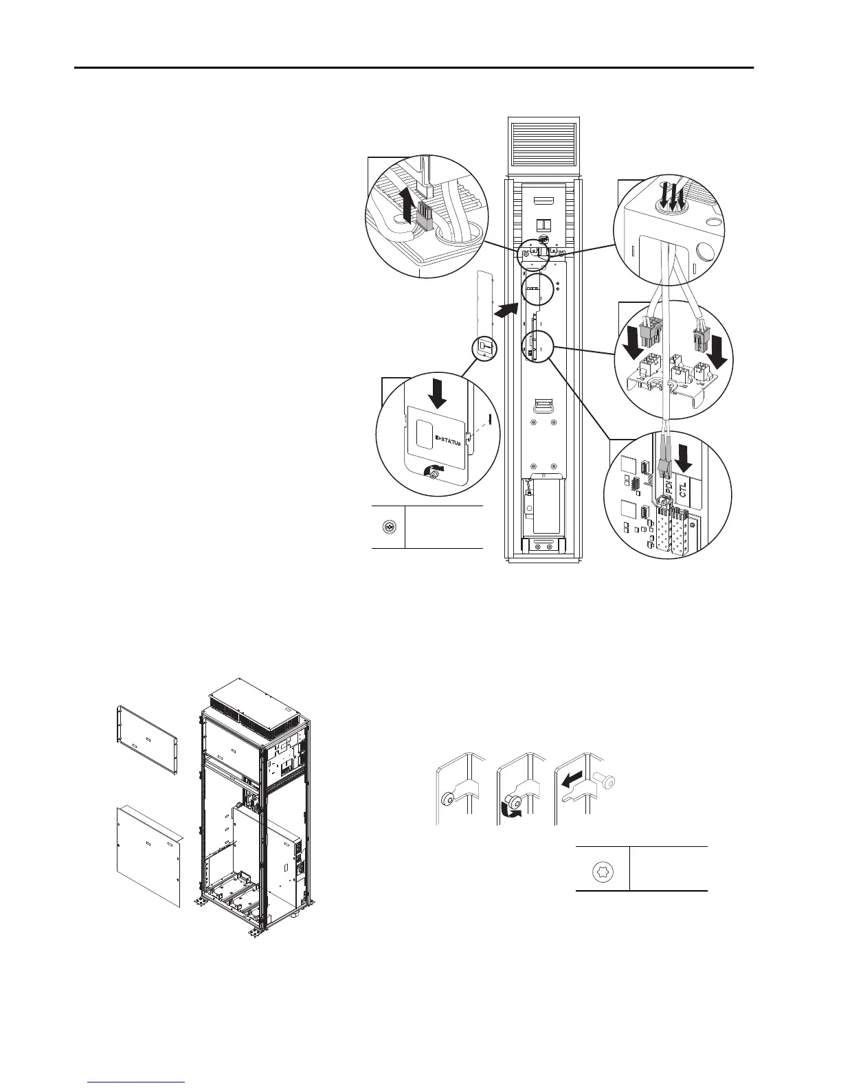
3. Connect the associated wire harnesses.
4. Install all applicable safety guards and apply the final torque as indicated.
a. Refer to this image for configurations that do not contain a DC precharge module:
a. Pull the wire harnesses through the top of
the power module.
b. Connect the wire harnesses.
c. Connect the Ethernet cable.
d. Connect the harness to the base of the DC
precharge module. (Only for DCPC
modules)
e. Install the connection faceplate and apply
the final torque as indicated.
e
d
c
b
a
Slotted Phillips
1.8 N•m +/- 10%
(16 lb•in +/- 10%)
Example of safety guard flanges:
M5.5
T25
4.8 N•m (23 lb•in)
The 800 mm (31.5 in.)cabinet configuration is shown and is typical of other sizes.
 Loading...


