Rockwell Automation Publication 750-IN105D-EN-P - June 2018 9
PowerFlex 750-Series Service Cart and DC Precharge Module Lift
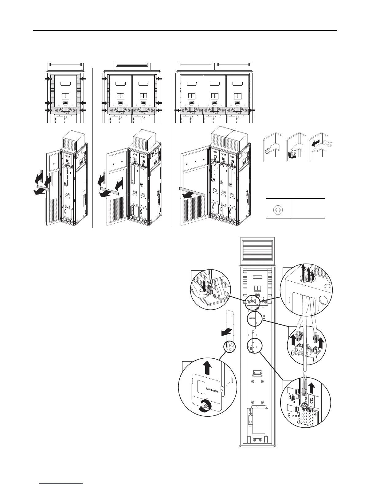
b. Refer to these images for configurations that contain a DC precharge module.
The mounting screws for safety guards can remain in the cabinet. The safety guard slides past the head of a loosened screw.
.
4. Disconnect and remove associated wire harnesses.
400 mm (15.7 in.)
Configuration
600 mm (23.6 in.)
Configuration
800 mm (31.5 in.)
Configuration
Example of safety guard flanges:
Front Views
M5.5
T25
4.8 N•m (23 lb•in)
a. Remove the connection faceplate.
b. Disconnect the wire harness from the DC precharge
module.
(Only for DCPC modules)
c. Disconnect the Ethernet cable.
d. Disconnect the remainder of the wire harnesses.
e. Pull the wire harnesses through the top of the power
a
b
c
d
e
 Loading...


