Rockwell Automation Publication 750-IN001O-EN-P - October 2014 157
Power Wiring Chapter 4
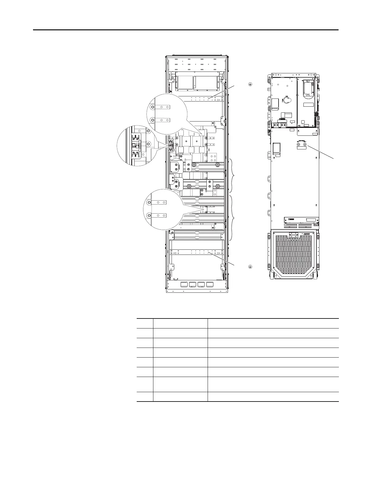
Figure 93 - Bus Bar and AC Power Rail Locations, Common DC Input Floor Mount Drives
Table 12 - Floor Mount Frame 8 Common DC Input
➊
➋
➌
➌
DC+
DC–
U / T1
V / T2
W / T3
PE
PE
➐
➍
➏
➎
Frame 8
Hot
Neutral
Hot
Neutral
No. Name Description
➊ DC Power Bus DC+, DC-
➋ Power Bus U/T1, V/T2, W/T3
➌ PE Grounding Bar Terminating point to chassis ground for incoming AC line and motor shield.
➍ Control Rail 120V AC control power supply connections. Top rail is hot.
➎ Control Power Circuit Breaker 120V AC control power supply circuit breaker.
➏ UPS Rail 120V AC Uninterruptible Power Supply (UPS) connections. Top rail is hot.
The UPS rail is only installed when the P30 UPS Control Bus option is selected.
➐ DC+ and DC- Bus Voltage Test Points
 Loading...


