EasyManuals Logo

Allen-Bradley PowerFlex 20-750-S1 User Manual

Allen-Bradley PowerFlex 20-750-S1
302 pages
To Next Page IconTo Next Page
To Previous Page IconTo Previous Page
Page #158 background imageLoading...
Page #158 background image
158 Rockwell Automation Publication 750-IN001O-EN-P - October 2014
Chapter 4 Power Wiring
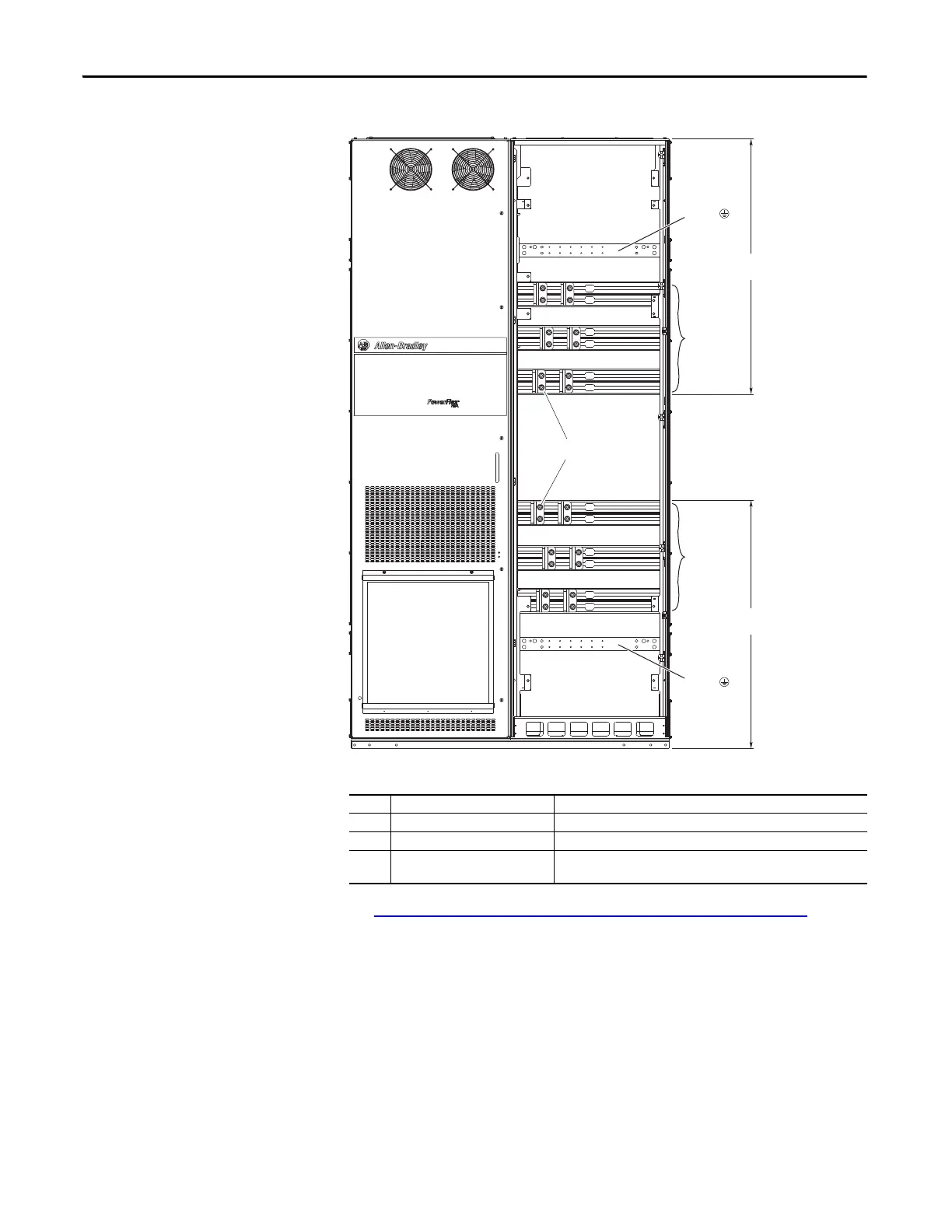
Figure 94 - Bus Bar Locations, Floor Mount Frame 8 Option P14 Wiring Bay
Table 13 - Floor Mount Frame 8 Wiring Bay
See Floor Mount Frames 8…10 Power Terminal L-Brackets on page 162 for
information on making cable connections on extruded bus bars.
No. Name Description
Power Bus R/L1, S/L2, T/L3
Power Bus U/T1, V/T2, W/T3
PE Grounding Bar Terminating point to chassis ground for incoming AC line and motor
shield.
R / L1
S / L2
T / L3
U / T1
V / T2
W / T3
PE
PE
964
(38.0)
936
(36.9)
L-brackets (2 per phase)

Table of Contents

Questions and Answers:

Question and Answer IconNeed help?

Do you have a question about the Allen-Bradley PowerFlex 20-750-S1 and is the answer not in the manual?

Allen-Bradley PowerFlex 20-750-S1 Specifications

General IconGeneral
BrandAllen-Bradley
ModelPowerFlex 20-750-S1
CategoryController
LanguageEnglish

Related product manuals