216 Rockwell Automation Publication 750-IN001O-EN-P - October 2014
Chapter 4 Power Wiring
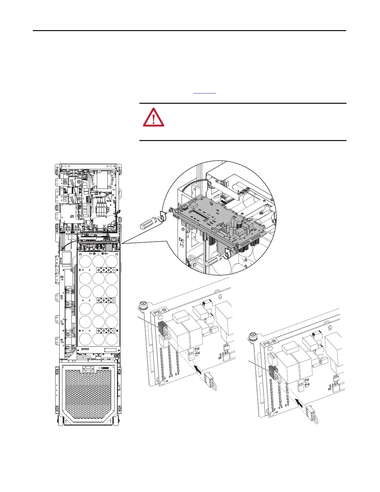
Floor Mount Frames 8…10 Drive Assembly Jumper Removal and
Storage
Frame 8…10 drive assemblies use jumper plugs to complete an electrical
connection when installed. Install or remove jumper plugs according to the
recommendations in Ta b le 30
.
Figure 119 - Frames 8…10 Drive Assembly PE-B Common Mode Jumper Location
Removal and installation the Inverter Power Control Board tray:
• Recommended torque = 1.86 N•m (16.0 lb•in)
• Recommended screwdriver = T20 Hexalobular
ATTENTION: Hazard of equipment damage exists if jumpers are not properly
disconnected or are set differently between drive assemblies. For Frame 8…10
drive assemblies, secure the disconnected jumper plug in the socket provided
and ensure that all drive assemblies are identically configured.
Disconnected
Connected
AC Input Drive Shown
 Loading...


