Do you have a question about the Allen + Roth 1599709 and is the answer not in the manual?
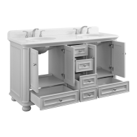
Assemble middle shelf moldings with middle shelf using dowels, cam bolts, and cam locks.
Attach middle shelf, back upper stretcher, and front stretcher to left upper side frame with cam locks.
Repeat procedure to attach right upper side frame to the assembly.
Attach top panel to the assembly using dowels, cam bolts, and cam locks.
Attach bottom shelf using 30 mm bolts and hex wrench.
Attach back middle/bottom stretchers and front stretcher to left lower side frame with cam locks.
Secure unit to wall using anchors and screws after leveling.
Install tipping restraint hardware to secure unit to wall studs.
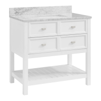
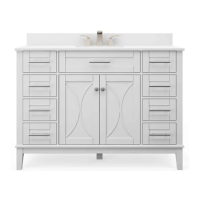
| Product Name | Allen + Roth 1599709 |
|---|---|
| Category | Indoor Furnishing |
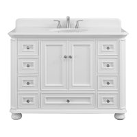
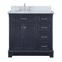
| Type | Bathroom Vanity |
| Mounting Location | Freestanding |
| Height (in) | 34.5 |
| Top Material | Cultured Marble |
| Sink Type | Integrated |
| Number of Sinks | 1 |
| Number of Drawers | 2 |
| Number of Doors | 2 |
| Hardware Finish | Brushed Nickel |
| Color/Finish Family | Gray |
| Cabinet Material | Wood |
| Color | Gray |
| Material | Wood |
| Style | Modern |