SECTION 3
SERVICE
075765 Page 49
Control Lever Adjustment
Control Lever Adjustment Procedure
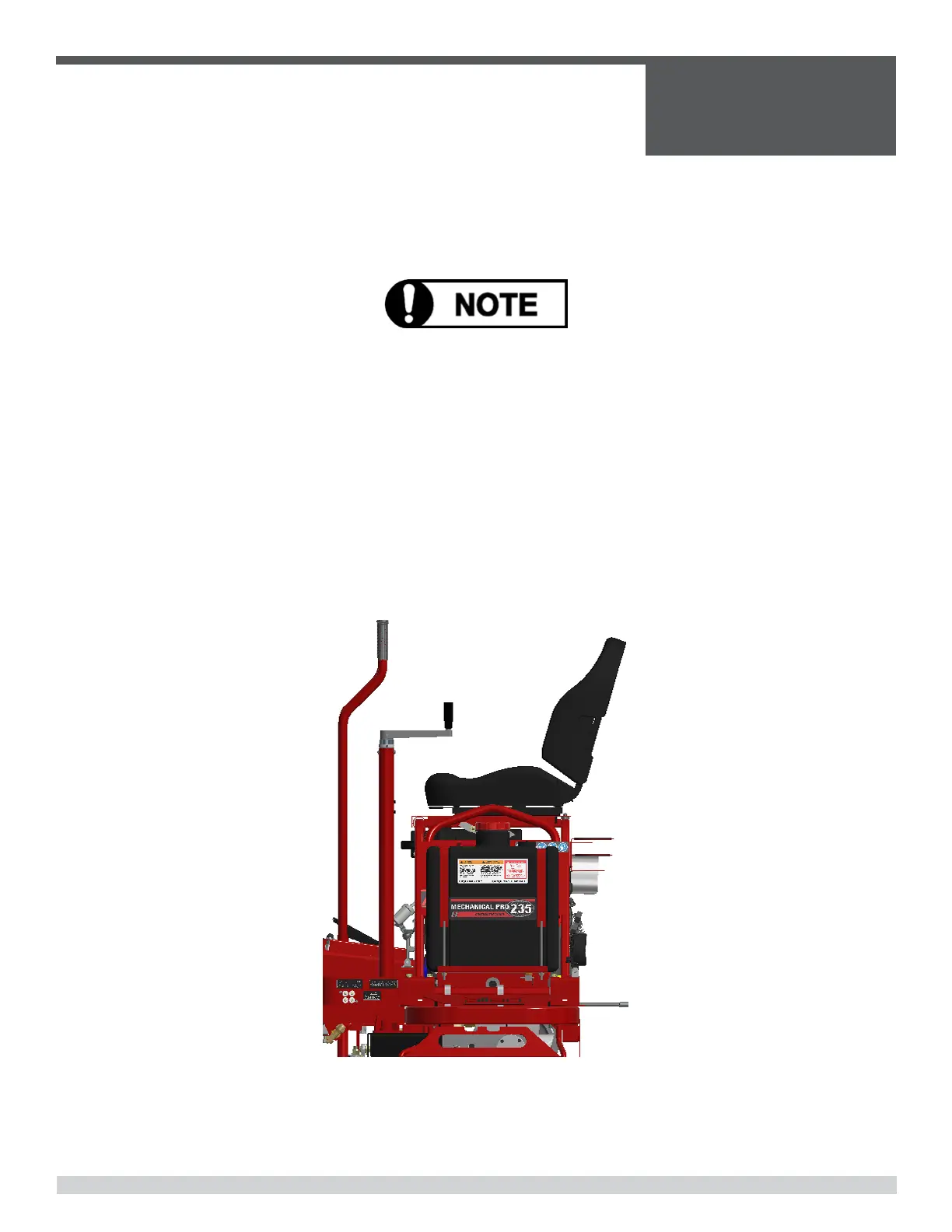
Be sure that the trowel is on a level surface. The control levers should line up evenly. If the levers
appear out of adjustment they can re-adjusted forwards or backwards as follows:
The trowel must be placed on a flat level surface that fully supports the blades on both rotors
1. Remove the lower bolts and nuts (3/8” fasteners) from both control levers [A] and loosen the
jam nuts.
2. Extend the rod end [B] to adjust the control levers backward
3. Shorten the rod end [B] to adjust the control levers forward
4. After the levers have been adjusted to the desired position, reassemble the bolts and nuts.
Tighten the jam nuts.
 Loading...