Page 1
©2008 Allied Air Enterprises Inc., a Lennox International Inc. Company
Phone: (803) 738−4000
Service Literature
TCA
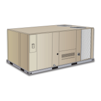
ROOFTOP UNITS
TCA−090−102−120−150 (10−08)
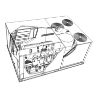
The TCA 7.5, 8.5 and 10 ton cooling package units are avail-
able in standard efficiency (090S, 102S, 120S) and high effi-
ciency (090H, 102H, 120H). The TCA 12.5 ton unit is avail-
able in standard efficiency only (150S). The TCA 090/150
series uses one cabinet size with cooling capacities of
93,000 to 140,000 Btuh (27.2 to 41 kW).
Optional electric heat is factory−or field−installed in TCA units.
Electric heat operates in single or multiple stages depending
on the kW input size. 7.5 kW to 45 kW heat sections are avail-
able for the TCA090 and 102 and 15 kW to 60 kW heat sec-
tions are available for the TCA120 and 150.
All units utilize two scroll compressors and are designed to
accept any of several different energy management thermo-
stat control systems with minimum field wiring. Factory or
field provided control options connect to the unit with jack
plugs. When "plugged in" the controls become an integral
part of the unit wiring.
Information contained in this manual is intended for use by
qualified service technicians only. All specifications are sub-
ject to change. Procedures outlined in this manual are pre-
sented as a recommendation only and do not supersede or
replace local or state codes.
If the unit must be lifted for service, rig unit by attaching four
cables to the holes located in the unit base rail (two holes at
each corner). Refer to the installation instructions for the prop-
er rigging technique.
WARNING
Improper installation, adjustment, alteration, service
or maintenance can cause property damage, person-
al injury or loss of life. Installation and service must
be performed by a licensed professional installer or
service agency.
WARNING
Refrigerant can be harmful if it is inhaled. Refrigerant
must be used and recovered responsibly.
Failure to follow this warning may result in person-
al injury or death.
ELECTROSTATIC DISCHARGE (ESD)
Precautions and Procedures
CAUTION
Electrostatic discharge can affect electronic
components. Take precautions during unit instal-
lation and service to protect the unit’s electronic
controls. Precautions will help to avoid control
exposure to electrostatic discharge by putting
the unit, the control and the technician at the
same electrostatic potential. Neutralize electro-
static charge by touching hand and all tools on an
unpainted unit surface before performing any
service procedure.
Table of Contents
Specifications 2. . . . . . . . . . . . . . . . . . . . . . . . . . . . . . . . .
Options 4. . . . . . . . . . . . . . . . . . . . . . . . . . . . . . . . . . . . . .
Electrical Data 6. . . . . . . . . . . . . . . . . . . . . . . . . . . . . . . .
Blower Data 8. . . . . . . . . . . . . . . . . . . . . . . . . . . . . . . . . .
I Unit Components 12. . . . . . . . . . . . . . . . . . . . . . . . . . . .
II Placement and Installation 24. . . . . . . . . . . . . . . . . . . .
III Start Up Operation 24. . . . . . . . . . . . . . . . . . . . . . . . . .
IV Charging 24. . . . . . . . . . . . . . . . . . . . . . . . . . . . . . . . . .
V Maintenance 26. . . . . . . . . . . . . . . . . . . . . . . . . . . . . . . .
VI Accessories 27. . . . . . . . . . . . . . . . . . . . . . . . . . . . . . . .
VII Wiring and Operating Sequence 33. . . . . . . . . . . . .