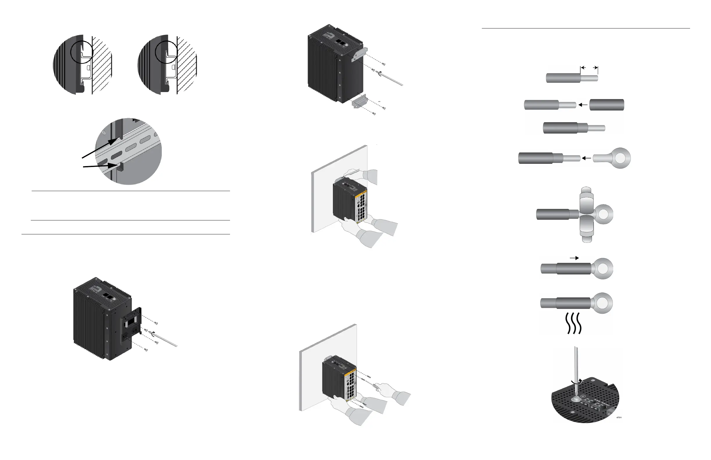
4. Carefully lower the switch so that the top flange on the DIN rail slides into the top slot
in the DIN rail bracket.
5. Visually inspect the bracket to verify that the DIN rail is now fitted into the top and
bottom slots on both the left and right sides.
Allied Telesis recommends installing DIN rail end clamps to the sides of the switch
to prevent damage or network traffic loss from vibration or shock. End clamps are
not available from Allied Telesis.
Installing the Switch on a Concrete Wall
To install the switch on a concrete wall, perform the following procedure:
1. Place the switch on a table.
2. Remove the pre-installed DIN rail bracket from the switch using a Phillips-head
screwdriver.
3. Install the two wall brackets to the back panel of the switch, with the four provided
screws.
4. Have a person hold the switch on the concrete wall at the selected location for the
device while you use a pencil or pen to mark the wall with the locations of the four
screw holes in the two wall brackets.
5. Use a drill and 1/4” carbide drill bit to pre-drill the four holes you marked in the
previous step. Please review the following guidelines:
Prior to drilling, set the drill to hammer and rotation mode. The mode breaks up the
concrete and cleans out the hole.
Allied Telesis recommends cleaning out the holes with a brush or compressed air.
6. Insert four anchors (not provided) into the holes.
7. Have a person hold the switch on the concrete wall at the selected location while you
secure it with four screws (not provided).
Connecting the Grounding Wire
To connect the grounding wire, perform the following procedure:
1. Strip 2.54cm (1.0 in.) of insulation from the end of the solid grounding wire
(recommended #16 AWG) with a wire insulator stripper.
2. Slide a heat-shrink tube over the grounding wire.
3. Slide the ring terminal lug over the stripped wire on the grounding wire.
4. Crimp the ring terminal lug with a wire crimping tool to secure it on the grounding wire.
5. Slide the heat-shrink tube over the shaft of the ring terminal lug.
6. Heat the heat-shrink tube to secure it on the wire and ring terminal lug.
7. Remove the grounding screw from the switch with a #2 Phillips-head screwdriver.
4 5 6

 Loading...


