Do you have a question about the Allied 4SCU14LE Series and is the answer not in the manual?
Read manual, follow warnings, comply with codes, and use R410A refrigerant.
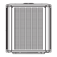
Follow Figure 1 for installation clearances and placement advice.
Details for slab and roof mounting procedures and requirements.
Field wiring must comply with NEC, CEC, CSA, and local codes.
Diagram illustrating slab mounting with ground level.
Shows thermostat, indoor, and outdoor unit connections for power and control.
Unit must be grounded per national/local codes to prevent injury or death.
Use R410A approved components, flush existing lines if needed.
Table showing recommended liquid and suction line diameters based on BTUH and length.
Isolate lines to prevent vibration and noise transmission to the building.
Consider sound ordinances and placement diagrams for optimal unit placement.
Use strapping material or wire ties to secure lines to joists or rafters at intervals.
Illustrates transitions using metal sleeves, wire ties, or hangers.
Shows how to install vertical runs, ensuring lines do not contact walls or structure.
Detailed steps for brazing refrigerant lines, including using nitrogen and protecting components.
POE oils absorb moisture; keep system closed and caps on until ready for connections.
Procedure for flushing systems with R22 to prepare for R410A.
Empty traps, residual oil can hinder heat transfer and clog TXV, voiding warranty.
Lists recovery bottles, machine, gauges for flushing R22 systems.
Steps for removing R22, connecting recovery equipment, and flushing the system.
Diagram shows connections for flushing using a recovery machine and R22 cylinder.
Detailed steps for vacuuming, breaking vacuum with nitrogen, and re-installing valve cores.
Explains TXV systems and provides TXV data for different models.
Table listing TXV models and their corresponding part numbers.
Step-by-step instructions for installing the TXV distributor and sensing bulb.
Covers diagrams, gauge requirements, and service valve operations.
Diagram illustrating the components of a metering device, including expansion valve.
Specifies pressure and hose ratings for R410A systems.
Explains the function and components of service valves and Schrader ports.
Covers accessing Schrader ports, opening, and closing service valves.
Details the ball type service valve and its operation.
Diagram illustrating the operation of a ball type service valve.
Methods for checking line set and unit connections for leaks using R410A and nitrogen.
Never use oxygen for purging or pressurizing; it can cause fire or explosion.
Steps for connecting gauges, introducing R410A and nitrogen for leak detection.
Critical steps for evacuating the system of noncondensables.
Critical for proper operation; noncondensables and water vapor cause corrosion.
Avoid deep vacuum to prevent arcing, compressor failure, and voiding warranty.
Connect gauges, vacuum pump, evacuate to 500 microns, break vacuum with nitrogen.
Procedures for starting up the air conditioning system.
Energize crankcase heater 24 hours before start-up to prevent compressor slugging.
Steps to verify proper operation before and during start-up.
Details on R410A charging, compatible oils, and charge adjustments for line set variations.
Table showing R410A pressures corresponding to various temperatures for charging.
Procedure for charging the system by weight, especially when void of refrigerant.
Method for charging when outdoor temperature is 65°F or above using subcooling.
Table showing target subcooling values for TXV systems based on outdoor temperature and model.
Table showing target approach values for TXV systems based on outdoor temperature and model.
Method for charging when outdoor temperature is 65°F or above using approach method.
Using pressures from Table 8 to check charge, not for initial charging.
Typical pressures for system operation at various conditions.
Table of typical liquid and suction pressures for various models and outdoor temperatures.
Description of how the outdoor unit and indoor blower operate.
Turn off all power supplies before maintenance to avoid electrical shock.
Inspect condenser coil, fan motor, lines, wiring, voltage, and amp-draw.
Clean coil, check lines for leaks, and clean condensate pan.
Clean/change filters, adjust blower speed, check belts, and wiring.
Comprehensive checklist for system start-up and performance verification.
Checks for electrical connections, filter, voltage, pressures, refrigerant charge, leaks, valves, and thermostat.
Diagram showing electrical connections for outdoor unit components like fan, compressor, and contactor.
Electric shock hazard; unit must be grounded per national and local codes.
Details the warranty coverage, limitations, and exclusions.
Covers warranty start, limitations on implied warranties, and exclusive warranty statement.
Details what is not covered, warranty on replacement parts, and exclusion of consequential damages.
| Type | Split System Air Conditioner |
|---|---|
| Compressor Type | Scroll |
| Refrigerant | R-410A |
| Voltage | 208/230V |
| Power Supply | 208/230V, 1 Phase, 60 Hz |
| Heating Capacity | Not Available |
| Operating Temperature (Heating) | Not applicable |
| Indoor Unit Dimensions (H x W x D) | Varies by model |
| Indoor Unit Weight | Varies by model |
| EER | Up to 11.5 EER |
| Energy Efficiency Ratio (EER) | Up to 11.5 EER |