Do you have a question about the Allied 4DHV Mini-Split Series and is the answer not in the manual?
Service manual for the 4DHV Mini-Split Series air conditioning units.
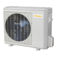
Technical specifications for the outdoor units, including capacity, dimensions, and electrical data.
Technical specifications for the wall-mounted indoor units, including capacity, dimensions, and electrical data.
Detailed dimensions for various outdoor unit models, provided in inches and millimeters.
Detailed dimensions for wall-mounted indoor units, provided in inches and millimeters.
Dimensions for the wall mounting plates used with indoor units, in inches and millimeters.
Clearance requirements for single and multiple outdoor unit installations.
Clearance requirements for indoor unit installation from walls, ceiling, and floor.
Cooling and heating capacity ratings for the 09 model at 115V across various temperature conditions.
Cooling and heating capacity ratings for the 12 model at 208/230V across various temperature conditions.
Cooling and heating capacity ratings for the 12 model at 115V across various temperature conditions.
Cooling and heating capacity ratings for the 12 model at 208/230V across various temperature conditions.
Cooling and heating capacity ratings for the 18 model at 208/230V across various temperature conditions.
Cooling and heating capacity ratings for the 24 model at 208/230V across various temperature conditions.
Cooling and heating capacity ratings for the 36 model at 208/230V across various temperature conditions.
Wiring diagrams for 115VAC outdoor units, illustrating component connections.
Wiring diagrams for 208/230VAC outdoor units, illustrating component connections.
Wiring diagrams for indoor units, showing connections to power and communication.
Description and function of each button on the wireless remote controller.
Explanation of the icons and indicators on the wireless remote display.
Instructions for setting temperature units, operation modes, and timers.
Procedure for setting unique addresses for indoor units connected to a centralized controller.
Procedure for operating the unit in Dry mode for dehumidification.
Steps to follow for performing a test run of the unit after installation.
Checklist to verify proper operation and safety during a test run.
Procedures for checking refrigerant leaks and purging air/moisture from the system.
Steps for charging refrigerant and evacuating the system after servicing.
Procedures for collecting refrigerant into the outdoor unit from the indoor circuit.
Location and meaning of LEDs on the outdoor unit's main control board.
Guidelines for adding refrigerant based on pipe diameter and length.
Tables showing cooling/heating capacity and pressure values in Fahrenheit.
Logic for outdoor fan speed control in cooling mode, including low ambient conditions.
Steps for removing the front panel and air filter of the indoor unit.
Procedures for removing the electrical cover and front panel assembly.
Steps for removing electrical parts and the coil temperature sensor (T2).
Instructions for disassembling components within the electronic control box.
Steps for disassembling and removing the evaporator from the indoor unit.
Procedures for removing the fan motor and step motor assemblies.
Steps for removing panel plates from specific outdoor unit models.
Steps for removing panel plates from the 4DHV1S24S outdoor unit model.
Steps for removing panel plates from the 4DHV1S36S outdoor unit model.
Disassembly instructions for electronic components in the 4DHV1S18S outdoor unit.
Disassembly instructions for electronic components in 4DHV1S24S and 4DHV1S36S outdoor units.
Steps for disassembling the fan motor assembly in 4DHV1S09S and 4DHV1S12S outdoor units.
Steps for disassembling the fan motor assembly in the 4DHV1S18S outdoor unit.
Steps for disassembling the fan motor assembly in the 4DHV1S24S outdoor unit.
Steps for disassembling the fan motor assembly in the 4DHV1S36S outdoor unit.
Procedure for removing and disassembling the four-way valve.
Steps for safely removing the compressor from the outdoor unit.
List of error codes displayed by indoor and outdoor units with their descriptions.
Diagnostic procedures for identifying and resolving issues based on error codes.
Checks for IPM continuity and normal P voltage readings.
Diagnosis and solution for EEPROM communication error (E0/F4).
Diagnosis and solution for communication malfunction between indoor and outdoor units (E1).
Diagnosis and solution for zero-crossing signal detection error (E2).
Diagnosis and solution for fan speed operating outside normal range (E3/F5).
Diagnosis for fan motor issues and potential PCB problems.
Diagnosis for temperature sensor open/short circuit errors.
Diagnosis and solution for refrigerant leakage detection error (EC).
Diagnosis and solution for IPM malfunction or IGBT over-current protection (P0).
Diagnosis and solution for over/under voltage protection (P1).
Diagnosis and solution for high temperature protection of IPM module (P2).
Diagnosis and solution for inverter compressor drive error (P4).
Resistance values for temperature sensors (T1, T2, T3, T4) across various temperatures.
Resistance values for the discharge temperature sensor (TP) across various temperatures.
| Series | 4DHV Mini-Split Series |
|---|---|
| Type | Ductless Mini-Split |
| Refrigerant | R-410A |
| Cooling Capacity | 9, 000 - 36, 000 BTU/h |
| Heating Capacity | 9, 000 - 36, 000 BTU/h |
| Voltage | 208/230V |
| HSPF | Up to 10.0 |
| Operating Temperature (Cooling) | 5°F to 122°F |
| Wi-Fi Compatible | Yes |