508067-01Issue 2016Page 52 of 75
Electronic Components (4DHV1S24S)
NOTE: Antistatic gloves must be worn when you
disassemble the electronic box.
NOTE: Remove the panel plate before disassembling the
fan.
1. Remove the connector for the compressor.
2. Pull out the two blue wires connected to the expansion
value (not applicable to AC units only)
3. Pull out connectors for the condenser coil temperature
sensor (T3), outdoor ambient temperature sensor (T4)
and discharge temperature sensor (TP).
4. Disconnect the expansion valve.
5. Remove electronic control box.
Compressor
Reactor
4-way valve
Fan Motor
EEV
T3, T4 and TP
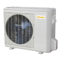
Electronic Components (4DHV1S36S)
NOTE: Antistatic gloves must be worn when you
disassemble the electronic box.
NOTE: Remove the panel plate before disassembling the
fan.
1. Remove the connector for the compressor.
2. Pull out the two blue wires connected with the four way
valve.
3. Pull out connectors of the condenser coil temp. sensor
(T3), outdoor ambient temp. sensor (T4) and discharge
temp. sensor (TP).
4. Disconnect the electronic expansion valve wire.
5. Disconnect the communication wire indoor PCB.
6. Disconnect the PFC inductor.
7. Remove electronic control box.
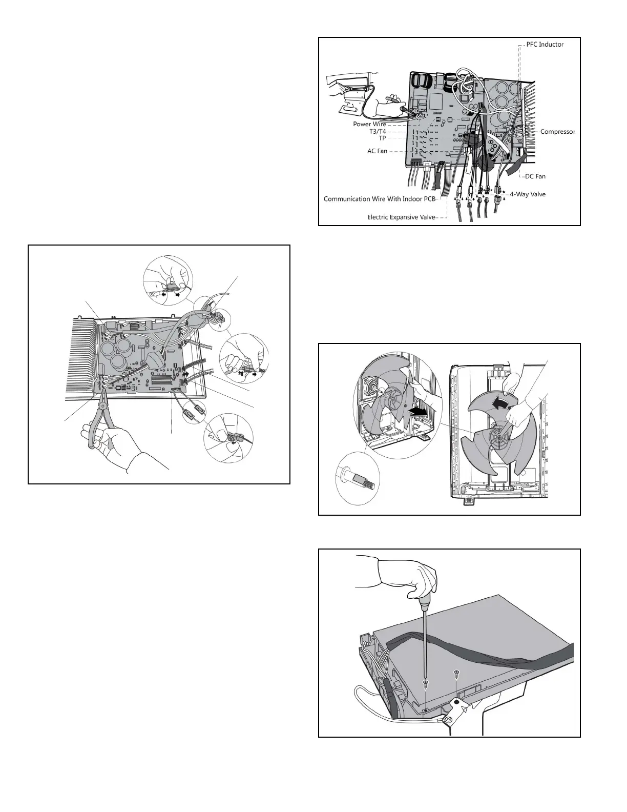
Fan Disassembly (4DHV1S09S and 4DHV1S12S)
NOTE: Antistatic gloves must be worn when you
disassemble the electronic box.
NOTE: Remove the panel plate before disassembling the
fan.
1. Remove nut securing the fan with a spanner.
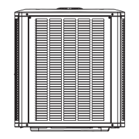
2. Remove the screws securing the top cover.