508067-01Issue 2016Page 60 of 75
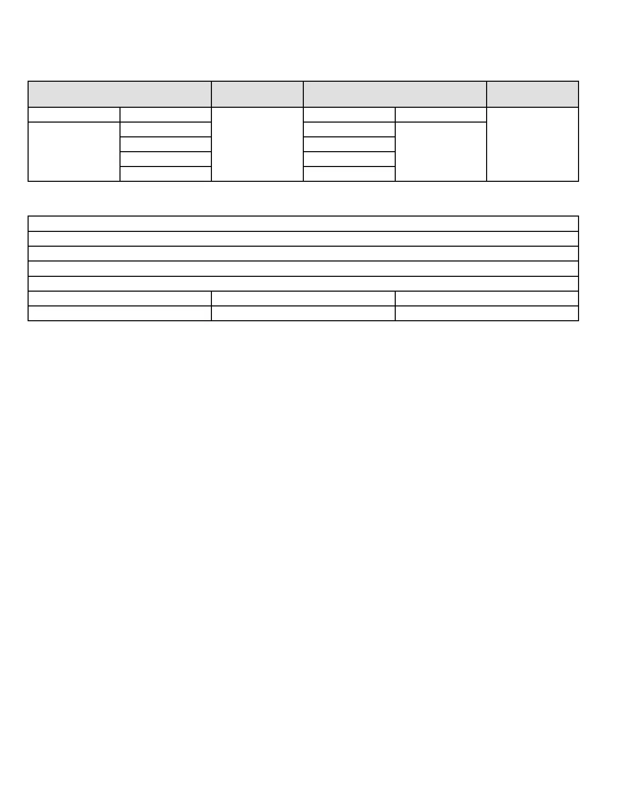
IPM Continuity Check
Turn o the power, let the large capacity electrolytic capacitors discharge completely, and dismount the IPM. Use a digital
tester to measure the resistance between P and UVWN; UVW and N.
Digital Tester
Normal Resistance
Value
Digital Tester
Normal Resistance
Value
(+) Red (-) Black
(Several M˄)
(+) Red (-) Black
(Several M˄)
P
N U
N
U V
V W
W (+) Red
Normal P Voltage
Normal Voltage for P and N
208-240V (1-phase))
In Standby
Around 310VDC
In Operation
With passive PFC module With partial active PFC module With fully active PFC module
>200VDC >310VDC >370VDC