508033-02Issue 2135Page 16 of 48
DIP Switch Settings
NOTE: All Comfort Sync
®
settings are set at the Comfort
Sync
®
Wi-Fi
®
thermostat. See Comfort Sync
®
installation
instruction. In Comfort Sync
®
communication system all
DIP switch and clippable link settings are ignored. For
conventional thermostats proceed with DIP switch and
clippable link settings as outlined in the following.
Heating Operation DIP Switch Settings
Switch 1 -- Thermostat Selection -- This unit may be
used with either a single-stage or two-stage thermostat.
The thermostat selection is made using a DIP switch which
must be properly positioned for the particular application.
The DIP switch is factory-positioned for use with a twostage
thermostat. If a single-stage thermostat is to be used, the
DIP switch must be repositioned.
1. Select “OFF” for two-stage heating operation controlled
by a two-stage heating thermostat (factory setting);
2. Select “ON” for two-stage heating operation controlled
by a single-stage heating thermostat. This setting
provides a timed delay before second-stage heat is
initiated.
Switch 2 -- Second Stage Delay (Used with Single-Stage
Thermostat Only) -- This switch is used to determine the
second stage on delay when a single-stage thermostat is
being used. The switch is factory-set in the OFF position,
which provides a 7-minute delay before secondstage heat
is initiated. If the switch is toggled to the ON position, it
will provide a 12-minute delay before secondstage heat is
initiated. This switch is only activated when the thermostat
selector jumper is positioned for SINGLEstage thermostat
use.
Switches 3 and 4 -- Blower-O Delay -- The blower-on
delay of 30 seconds is not adjustable. The blower-o delay
(time that the blower operates after the heating demand
has been satised) can be adjusted by moving switches
3 and 4 on the integrated control. The unit is shipped
from the factory with a blower-o delay of 90 seconds.
The blower o delay aects comfort and is adjustable to
atisfy individual applicationsAdjust the blower o delay to
achieve a supply air temperature between 90° and 110°F at
the exact moment that the blower is de-energized. Longer
o delay settings provide lower supply air temperatures;
shorter settings provide higher supply air temperatures.
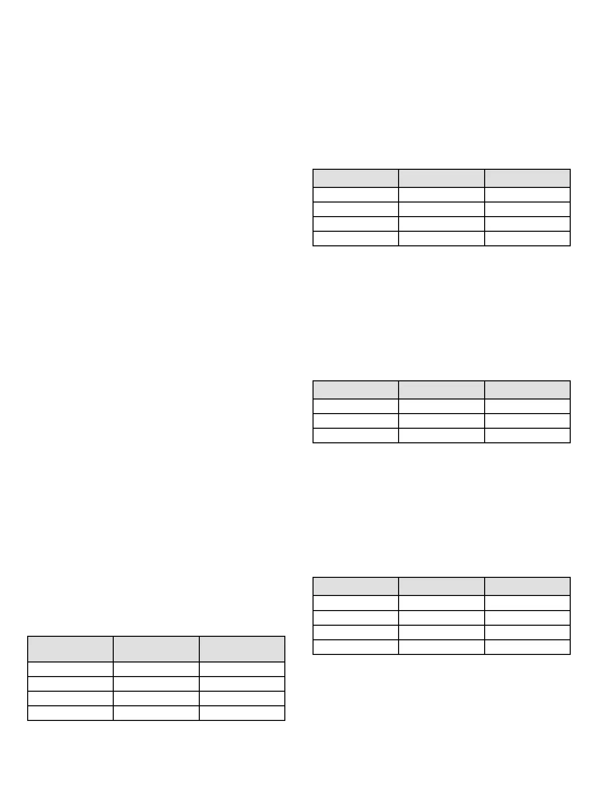
Table 6 provides the blower o timings that will result from
dierent switch settings.
Blower O Delay
Seconds
Switch 3 Switch 4
60 On O
90 (factory) O O
120 O On
180 On On
Table 6. Blower O Delay Switch Settings
Indoor Blower Operation DIP Switch Settings
Switches 5 and 6 -- Cooling Mode Blower Speed --
The unit is shipped from the factory with the dip switches
positioned for high speed (4) indoor blower motor operation
during the cooling mode. Table 7 provides the cooling mode
blower speeds that will result from dierent switch settings.
Switches 5 and 6 set the blower cfm for secondstage cool.
The integrated control automatically ramps down to 70% of
the second-stage cfm for rst-stage cfm. Refer to tables for
corresponding cfm values.
Speed Switch 5 Switch 6
Low On On
Medium Low O On
Medium High On O
High (factory) O O
Table 7. Cooling Mode Blower Speeds
Switches 7 and 8 -- Cooling Blower Speed Adjustment
-- The unit is shipped from the factory with the dip switches
positioned for NORMAL (no) adjustment. The dip switches
may be positioned to adjust the blower speed by +10% or
-10% to better suit the application. Table 8 below provides
blower speed adjustments that will result from dierent
switch settings. Refer to tables for corresponding cfm
values.
Adjustment Switch 7 Switch 8
+10% (approx) On O
Factory Default O O
-10% (approx) O O
Table 8. Cooling Blower Speed Adjustment
Switches 9 and 10 -- Cooling Mode Blower Speed
Ramping -- Blower speed ramping may be used to
enhance dehumidication performance. The switches
are factory set at option A which has the greatest eect
on dehumidication performance. Table 9 provides the
cooling mode blower speed ramping options that will result
from dierent switch settings. The cooling mode blower
speed ramping options are detailed below.
Ramping Switch 9 Switch 10
A (Factory) O O
B O On
C On O
D On On
Table 9. Cooling Mode Blower Speed Ramping