508297-01Page 2 of 57 Issue 2219
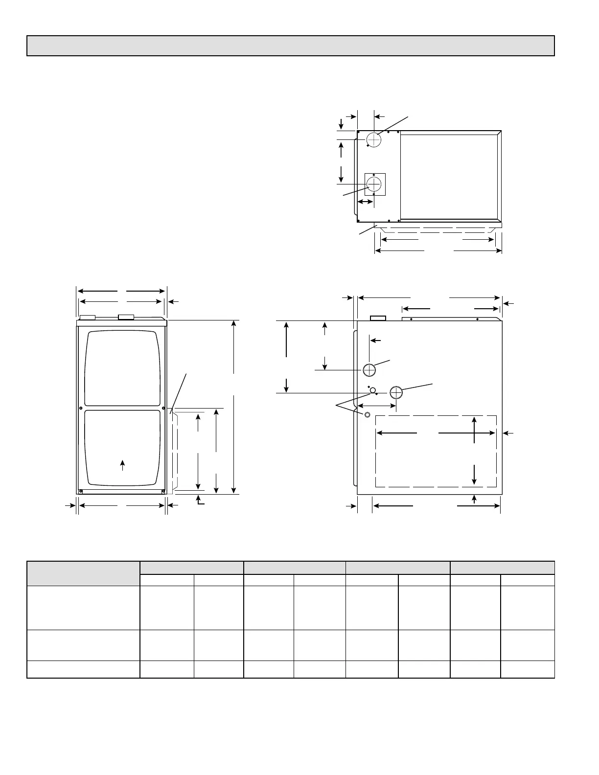
Front View
Top View
Side View
3/4
(19)
B
33
(838)
A
1
Bottom Return
Air Opening
9/16
(14)
Air Flow
C
3/4
(19)
14-3/4
(375)
16
(406)
2
Optional
Side Return
Air Filter Kit
(either side)
5/8
(16)
19-7/16 (494)
27-3/4 (705)
6-1/2 (165)
(either side)
14
(356)
Condensate
Trap Connection
(either side)
Electrical Inlet
(either side)
9 (229) Right
6-9/16 (167) Left
Gas Piping Inlet
(either side)
2 (51) (either side)
9/16
(14)
1 (25)
Front Panel
1
Bottom Return
Air Opening
3-1/4
(83)
12-5/8 (321)
(either side)
23
(584)
1
Side Return
Air Opening
(either side)
1-15/16 (49)
1-1/2
(38)
23-1/2 (597)
Supply Air
Opening
2 (51)
2-7/8
(73)
Exhaust Air
Outlet
Combustion
Air Intake
2
Optional
Side Return
Air Filter Kit
(either side)
23-3/4 (603)
25 (635)
3-3/8
(86)
D
1
NOTE - C*20 and D*20 (5 Ton) size units installed in upow
applications that require air volumes of 1800 cfm (850 L/s) or greater
must have one of the following:
1. Single side return air with transition, to accommodate 20 x 25 x 1
in. (508 x 635 x 25 mm) cleanable air lter. (Required to maintain
proper air velocity.)
2. Single side return air with optional “RAB” Return Air Base.
3. Bottom return air.
4. Return air from both sides.
5. Bottom and one side return air.
See “Blower Performance Tables” for additional information.
2
Optional External Side Return Air Filter kit is not for use with optional
Return Air Base.
* Consider sizing requirements for optional IAQ equipment before
cutting side return opening.
Unit Dimensions
Model
A B C D
in. mm in. mm in. mm in. mm
030-08
045-12
070-12
17-1/2 446 16-3/8 416 16 406 7-5/8 194
090-16
110-20
21 533 19-7/8 505 19-1/2 495 9-3/8 238
135-20 24-1/2 622 23-3/8 594 23 584 11-1/8 283