508297-01 Page 39 of 57Issue 2219
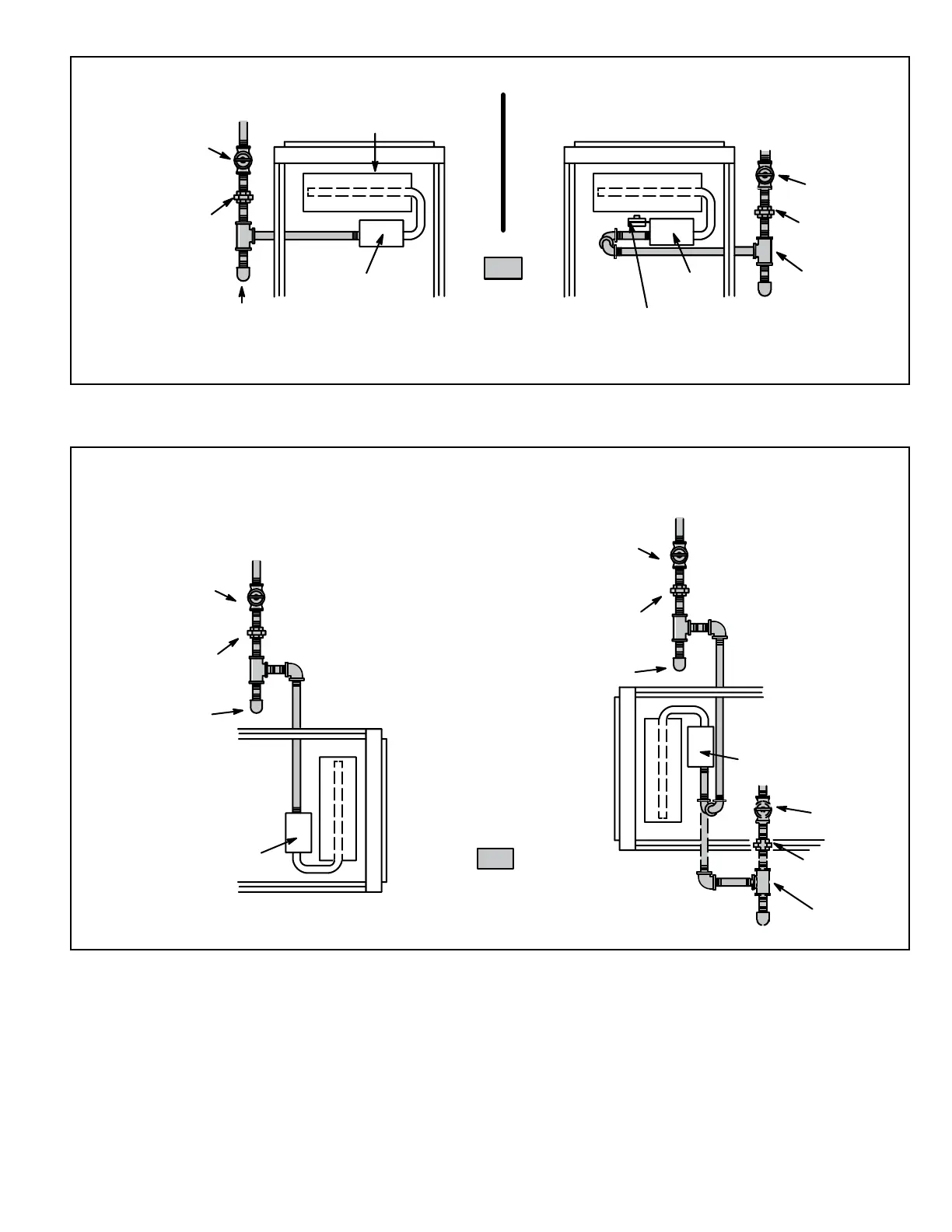
Figure 61. Upow Applications
Possible Gas Piping Congurations
NOTE - BLACK IRON PIPE ONLY TO BE ROUTED INSIDE OF CABINET
FIELD
PROVIDED
AND INSTALLED
GROUND
JOINT
UNION
DRIP LEG
MANUAL
MAIN SHUT-OFF
VALVE
Upflow Application
Right Side Piping
(Alternate)
Gas Valve
In LP/Propane applications, a 4” BIP nipple must be
installed to allow clearance for the low inlet pressure switch.
GROUND
JOINT
UNION
Upflow Application
Left Side Piping
(Standard)
DRIP LEG
MANUAL
MAIN SHUT-OFF
VALVE
AUTOMATIC
GAS VALVE
(with manual
shut-off valve)
Gas Valve
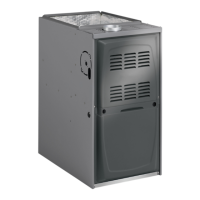
Horizontal Applications
Possible Gas Piping Configurations
NOTE - BLACK IRON PIPE ONLY TO BE ROUTED INSIDE OF CABINET
FIELD
PROVIDED
AND INSTALLED
GROUND
JOINT
UNION
DRIP LEG
MANUAL
MAIN SHUT-OFF
VALVE
Horizontal Application
Right-Side Air Discharge
Gas Valve
GROUND
JOINT
UNION
DRIP LEG
MANUAL
MAIN SHUT-OFF
VALVE
GROUND
JOINT
UNION
DRIP LEG
MANUAL
MAIN SHUT-OFF
VALVE
Horizontal Application
Left-Side Air Discharge
Gas Valve
Figure 62. Horizontal Applications
Possible Gas Piping Congurations