508148-01Issue 2128Page 2 of 75
Technical Specications - A96US2V
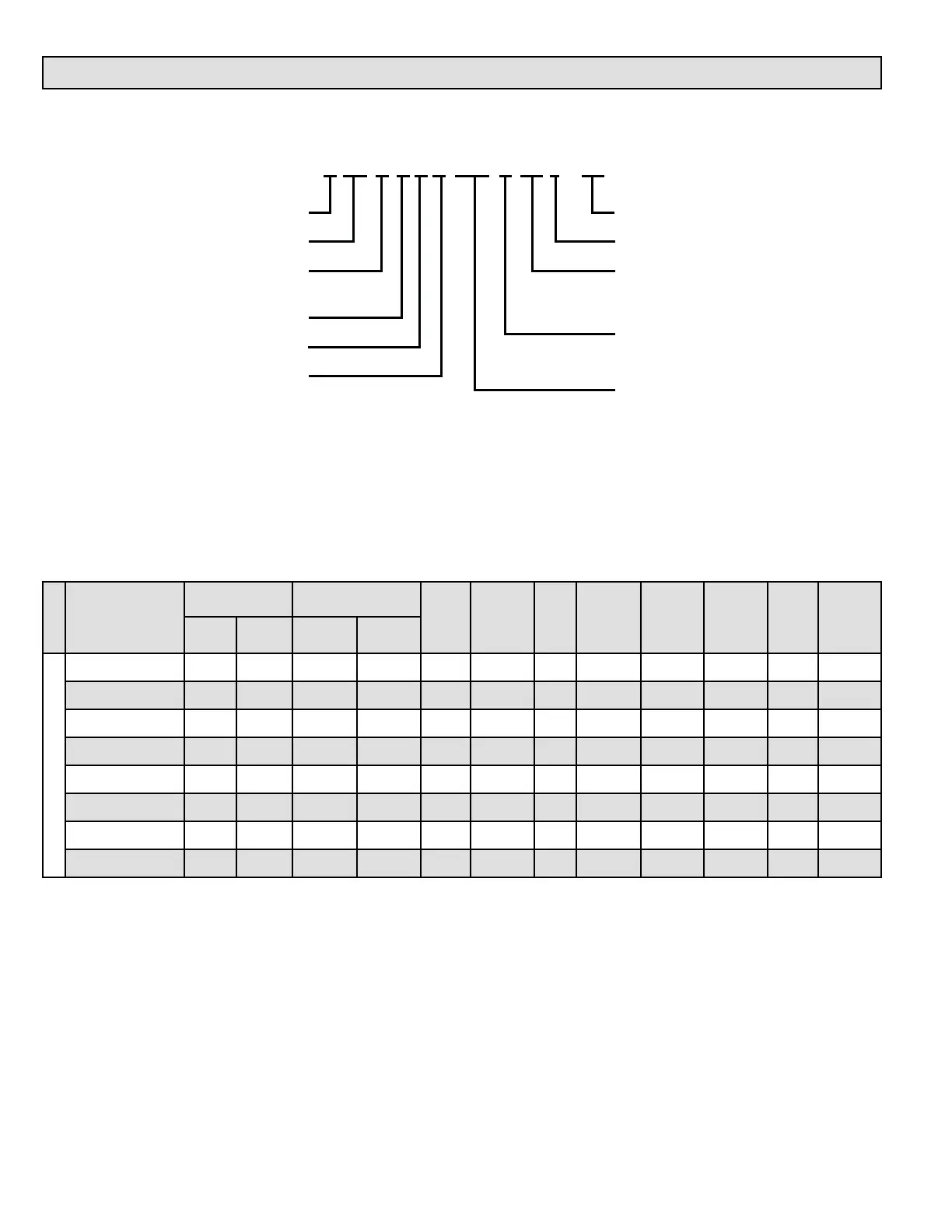
MODEL NUMBER GUIDE
PHYSICAL AND ELECTRICAL DATA
Model
1st Stage 2nd Stage
AFUE
(ICS)
Nominal
Cooling
Capacity
Gas
Inlet
(in.)
Volts/
Hz/
Phase
Max. Time
Delay
Breaker
or Fuse
Nominal
F.L.A.
Trans.
(V.A.)
Approx.
Shipping
Weight
(lbs.)
Input
(Btuh)
Output*
(Btuh)
Input
(Btuh)
Output*
(Btuh)
UPFLOW/HORIZONTAL
A96US2V045B12S 29,000 28,000 44,000 42,000 96.0 3 1/2 120-60-1 15 7.7 40 130
A96US2V070B12S 43,000 41,000 66,000 62,000 96.0 3 1/2 120-60-1 15 7.7 40 138
A96US2V090C12S 57,000 55,000 88,000 84,000 96.0 3 1/2 120-60-1 15 7.7 40 154
A96US2V090C16S 57,000 55,000 88,000 85,000 96.0 4 1/2 120-60-1 15 10.1 40 165
A96US2V090C20S 57,000 55,000 88,000 85,000 96.0 5 1/2 120-60-1 20 12.8 40 166
A96US2V110C16S 72,000 70,000 110,000 105,000 96.0 4 1/2 120-60-1 15 10.1 40 173
A96US2V110C20S 72,000 70,000 110,000 106,000 96.0 5 1/2 120-60-1 20 12.8 40 174
A96US2V135D20S 88,000 84,000 132,000 126,000 96.0 5 1/2 120-60-1 20 12.8 40 188
Note: For vent length and clearances to combustibles, please reference installation instructions.
* Outputs shown are High Fire, 100% rate, Low Fire is 67% of shown output.
Numeric Code
S = Stainless Steel Heat Exchanger
12 = 3 Ton add on cooling
16 = 4 Ton add on cooling
20 = 5 Ton add on cooling
B = 17.5 Width
C = 21.0 Width
D = 24.5 Width
Heating Input x 1000
A = Flagship
96 = 96% Efficiency
U = Upflow/Horizontal
D = Downflow
S = Communicating
2 = 2 Stage
V = Variable Speed
A 96 U S 2 V 110 C 16 S - 01
 Loading...


