Paragraphs 211B-213
ALLiS-CHALMERS
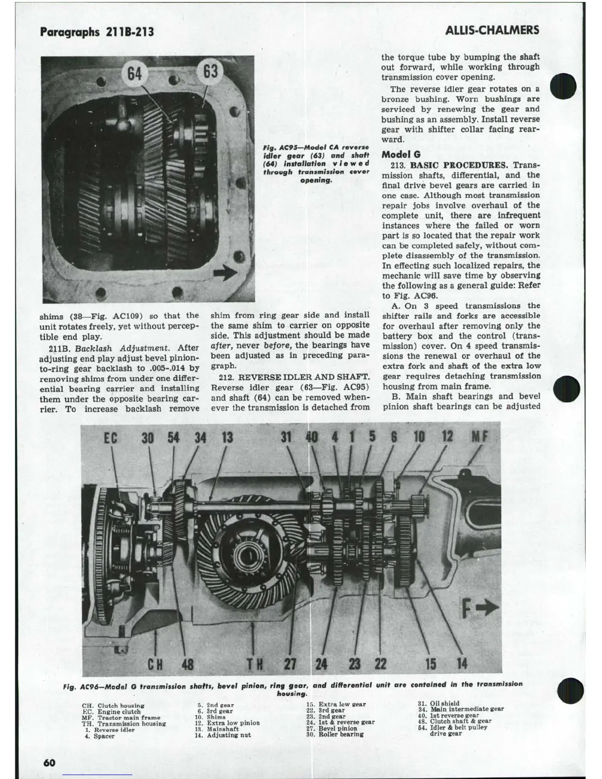
¥ig. AC95-Model CA reverse
idler gear (63) and shaft
(64) installation viewed
through transmission cover
opening.
shims (38—Fig. AC109) so that the
unit rotates freely, yet without percep-
tible end play.
211B.
Backlash Adjustment. After
adjusting end play adjust bevel pinion-
to-ring gear backlash to .005-.014 by
removing shims from under one differ-
ential bearing carrier and installing
them under the opposite bearing car-
rier. To increase backlash remove
shim from ring gear side and install
the same shim to carrier on opposite
side.
This adjustment should be made
after, never before, the bearings have
been adjusted as in preceding para-
graph.
212.
REVERSE IDLER AND SHAFT.
Reverse idler gear (63—Fig. AC95)
and shaft (64) can be removed when-
ever the transmission is detached from
the torque tube by bumping the shaft
out forward, while working through
transmission cover opening.
The reverse idler gear rotates on a
bronze bushing. Worn bushings are
serviced by renewing the gear and
bushing as an assembly. Install reverse
gear with shifter collar facing rear-
ward.
Model G
213.
BASIC PROCEDURES. Trans-
mission shafts, differential, and the
final drive bevel gears are carried in
one case. Although most transmission
repair jobs involve overhaul of the
complete unit, there are infrequent
instances where the failed or worn
part is so located that the repair work
can be completed safely, without com-
plete disassembly of the transmission.
In effecting such localized repairs, the
mechanic will save time by observing
the following as a general guide: Refer
to Fig. AC96.
A. On 3 speed transmissions the
shifter rails and forks are accessible
for overhaul after removing only the
battery box and the control (trans-
mission) cover. On 4 speed transmis-
sions the renewal or overhaul of the
extra fork and shaft of the extra low
gear requires detaching transmission
housing from main frame.
B.
Main shaft bearings and bevel
pinion shaft bearings can be adjusted
30
54 34 13
3V
40 4 1 S S ie 12 MF
CH
48
T
M
27 24
Fig, AC96-Modet G transmission shafts, bevel pinion, ring gear, and differential unit are contained in the transmission
housing.
CH. Clutch housing
KC.
Engine clutch
MF.
Tractor main frame
TH.
Transmission housing
1.
Reverse idler
4.
Spacer
5.
2nd gear
6. 3rd gear
10.
Shims
12.
Extra low pinion
13.
Mainshaft
14.
Adjusting nut
15.
Extra low gear
22.
Brd gear
23.
2nd gear
24.
1st
&
reverse gear
27.
Bevel pinion
30.
Roller bearing
31.
Oil shield
34.
Main intermediate gear
40.
1st reverse gear
48.
Clutch shaft
&
gear
64.
Idler
&
helt pulley
drive gear
60