ALLIS-CHALMERS
Paragraphs 214-218
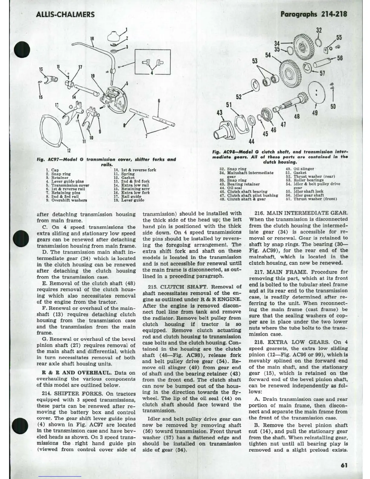
Fig, ilC97—Model 6 transmission
cover,
shifter forks and
rath.
10.
lst
&
reverse fork
11.
Spring
12.
Gasket
13.
2nd
&
3rd fork
14.
Extra low rail
15.
Retaining sere
16.
Extra low fork
17.
Rail guide
19.
Lever guide
1.
Cap
2.
Snap ring
3.
Retainer
4.
Lever guide pins
5.
Transmission cover
6. 1st & reverse rail
7.
Retaining* pins
8. 2nd & 3rd rail
9. Overshift washen
34
53
50
49
Fig, AC9<—Model G clutch
shaft,
and transmission
inter-
mediate gears. All of these parts are contained in the
clutch housing.
32.
Snap ring
34.
Mainahaft intermediate
gear
35.
Snap ring
43.
Bearing retainer
44.
Oil seal
46.
Clutch shaft bearing
47.
Clutch shaft pilot bushing
48.
Clutch shaft
&
gear
49.
Oil Blinger
51.
Gasket
52.
Thrust washer (rear)
53.
Roller bearings
54.
Idler & belt pulley drive
gear
55.
Idler shaft lock
56.
Idler gear shaft
57.
Thrust washer (front)
after detaching transmission housing
from main frame.
C.
On 4
speed transmissions
the
extra sliding and stationary
low
speed
gears
can be
renewed after detaching
transmission housing from main frame.
D.
The
transmission main shaft
in-
termediate gear
(34)
which
is
located
in
the
clutch housing
can be
renewed
after detaching
the
clutch housing
from
the
transmission case.
E.
Removal
of the
clutch shaft
(48)
requires removal
of the
clutch hous-
ing which also necessitates removal
of
the
engine from
the
tractor.
F. Renewal or overhaul
of
the main-
shaft
(13)
requires detaching clutch
housing from
the
transmission case
and
the
transmission from
the
main
frame.
G. Renewal
or
overhaul
of
the bevel
pinion shaft
(27)
requires removal
of
the main shaft
and
differential, which
in turn necessitates removal
of
both
rear axle shaft housing units.
R&R AND OVERHAUL. Data
on
overhauling
the
various components
of this model are outlined below.
214.
SHIFTER FORKS.
On
tractors
equipped with
3
speed transmissions,
these parts
can be
renewed after
re-
moving
the
battery
box and
control
cover.
The
gear shift lever guide pins
(4) shown
in Fig.
AC97
are
located
in the transmission case and have bev-
eled heads as shown. On 3 speed trans-
missions
the
right hand guide
pin
(viewed from control cover side
of
transmission) should
be
installed with
the thick side
of the
head up;
the
left
hand
pin is
positioned with
the
thick
side down.
On 4
speed transmissions
the pins should
be
installed
by
revers-
ing
the
foregoing arrangement.
The
extra shift fork
and
shaft
on
these
models
is
located
in the
transmission
and
is not
accessible
for
renewal until
the main frame is disconnected, as out-
lined
in a
preceding paragraph.
215.
CLUTCH SHAFT. Removal
of
shaft necessitates removal
of the en-
gine as outlined under R&R ENGINE.
After
the
engine
is
removed discon-
nect fuel line from tank
and
remove
the radiator. Remove belt pulley from
clutch housing
if
tractor
is so
equipped. Remove clutch actuating
rod and clutch housing
to
transmission
case bolts and the clutch housing. Con-
tained
in the
housing
are the
clutch
shaft (48—Fig. AC98), release fork
and belt pulley drive gear
(54). Re-
move
oil
slinger
(49)
from gear
end
of shaft and
the
bearing retainer
(43)
from
the
front
end. The
clutch shaft
can
now be
bumped
out of the
hous-
ing
in the
direction towards
the fly-
wheel.
The lip of the oil
seal
(44) on
clutch shaft should face toward
the
transmission.
Idler and belt pulley drive gear
can
now
be
removed
by
removing shaft
(56) toward transmission. Front thrust
washer
(57) has a
flattened edge
and
should
be
installed
on
transmission
side
of
gear
(54).
216.
MAIN INTERMEDIATE GEAR.
When
the
transmission
is
disconnected
from
the
clutch housing
the
intermed-
iate gear
(34) is
accessible
for re-
moval
or
renewal. Gear
is
retained
to
shaft
by
snap rings. The bearing (30—
Fig. AC99),
for the
rear
end of the
mainshaft, which
is
located
in the
clutch housing, can now be renewed.
217.
MAIN FRAME. Procedure
for
removing this part, which
at its
front
end is bolted to the tubular steel frame
and
at its
rear end
to
the transmission
case,
is
readily determined after
re-
ferring
to the
unit. When reconnect-
ing
the
main frame (cast frame)
be
sure that
the
sealing washers
of cop-
per
are in
place under
the two
lower
nuts where the tube bolts to the trans-
mission case.
218.
EXTRA
LOW
GEARS.
On 4
speed gearsets,
the
extra
low
sliding
pinion (12—Fig. AC96
or
99), which
is
movably splined
on the
forward
end
of
the
main shaft,
and the
stationary
gear
(15),
which
is
retained
on the
forward
end of the
bevel pinion shaft,
can
be
renewed independently
as fol-
lows:
A. Drain transmission case and rear
portion
of
main frame, then discon-
nect and separate the main frame from
the front
of the
transmission case.
B.
Remove
the
bevel pinion shaft
nut (14),
and
pull
the
stationary gear
from the shaft. When reinstalling gear,
tighten
nut
until
all
bearing play
is
removed
and a
slight preload exists.
61