Paragraphs 219-226
ALLIS-CHALMERS
16
19
18 17
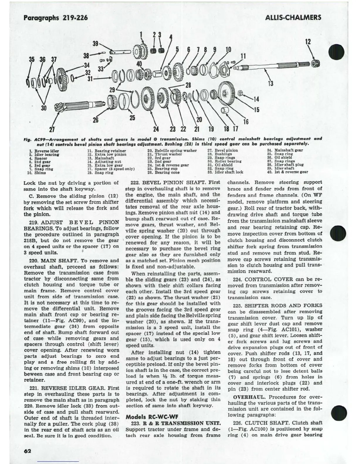
Pig, AC99-Arrangement of shafts and gears In model O transmission. Shims (10} control mainshaft bearings adiustment and
nut (14)
controls
bevel pinion shaft bearings adiustment.
Bushing
(28) in third speed gear can be purchased separately.
1.
Reverse idler
2.
Idler hearing
4.
Spacer
6. 2nd gear
6. Srd gear
7. Snap ring
10.
Shims
11.
Bearing retainer
12.
Extra low pinion
13.
Mainshaft
14.
Adjusting
nut
15.
Extra low gear
17.
Spacer
(3
speed only)
19.
Snap ring
20.
Belville spring washer
21.
Thrust washer
22.
3rd gear
23.
2nd gear
24.
1st
& reverse uewr
25.
Bearing cup
26.
Bearing cone
27.
Bevel pinion
28.
Bushings
29.
Snap rings
30.
Roller hearing
31.
Oil shield
32.
Snap ring
83.
Idler Bhaft lock
34.
Mainshaft gear
36.
Snap ring
36.
Oil shield
87.
Snap rings
88.
Idler shaft plug
39.
Idler shaft
40.
let
& reverse gear
Lock
the nut by
driving
a
portion
of
same into
the
shaft
C.
Remove
the
sliding pinion
(12)
by removing the set screw from shifter
fork which will release
the
fork
and
the pinion.
219.
ADJUST BEVEL PINION
BEARINGS. To adjust bearings, follow
the procedure outlined
in
paragraph
218B,
but do not
remove
the
gear
on
4
speed units or the spacer
(17) on
3 speed units.
220.
MAIN SHAFT.
To
remove
and
overhaul shaft, proceed
as
follows:
Remove
the
transmission case from
tractor
by
disconnecting same from
clutch housing
and
torque tube
or
main frame. Remove control cover
unit from side
of
transmission case.
It
is not
necessary
at
this time
to re-
move
the
differential unit. Remove
main shaft front
cap or
bearing
re-
tainer (11—Fig. AC99),
and the in-
termediate gear
(34)
from opposite
end
of
shaft. Bump shaft forward
out
of case while removing gears
and
spacers through control (shift lever)
cover opening. After renewing worn
parts adj ust bearings
to
zero
end
play
and a
free rolling
fit by add-
ing or removing shims (10) interposed
beween case and front bearing cap
or
retainer.
221.
REVERSE IDLER GEAR. First
step
in
overhauling these parts
is to
remove the main shaft as in paragraph
220.
Remove idler lock (33) from out-
side
of
case
and
pull shaft rearward.
Outer
end of
shaft
is
threaded inter-
nally
for a
puller. The cork plug
(38)
in
the
rear end
of
shaft acts
as an oil
seal. Be sure
it is in
good condition.
222.
BEVEL PINION SHAFT. First
step
in
overhauling shaft
is to
remove
the engine,
the
main shaft,
and the
differential assembly which necessi-
tates removal
of the
rear axle hous-
ings.
Remove pinion shaft nut (14) and
bump shaft rearward
out of
case.
Re-
move gears, thrust washer,
and Bel-
ville spring washer
(20) out
through
cover opening.
If the
pinion
is to be
renewed
for any
reason,
it
will
be
necessary
to
purchase
the
bevel ring
gear also
as
they
are
furnished only
as
a
matched set. Pinion mesh position
is fixed and non-adjustable.
When reinstalling
the
parts, assem-
ble
the
sliding gears
(23) and
(24),
as
shown with their shift collars facing
each other. Install
the 3rd
speed gear
(22)
as
shown. The thrust washer
(21)
for this gear should
be
installed with
the grooves facing
the
3rd speed gear
and plain side facing the Belville spring
washer
(20), as
shown.
If the
trans-
mission
is a 3
speed unit, install
the
spacer
(17)
instead
of the
special
low
gear
(15),
which
is
used only
on 4
speed units.
After installing
nut (14)
tighten
same
to
adjust bearings
to a
just per-
ceptible preload.
If
only the bevel pin-
ion shaft is in the case, the correct pre-
load
is
when
^ lb. of
torque meas-
ured
at
end
of
a one-ft. wrench or arm
is required
to
rotate
the
shaft
in its
bearings. After adjustment
is com-
pleted, lock
the nut by
staking thin
section
of
same into shaft keyway.
Models RC-WC-WF
223.
R&R
TRANSMISSION UNIT.
Support tractor under frame
and de-
tach rear axle housing from frame
channels. Remove steering support
brace
and
fender rods from front
of
fenders
and
frame channels. (On WF
model, remove platform
and
steering
gear.) Roll rear
of
tractor back, with-
drawing drive shaft
and
torque tube
from the transmission mainshaft sleeve
and rear bearing retaining
cap. Re-
move inspection cover from bottom
of
clutch housing
and
disconnect clutch
shifter fork spring from transmission
stud
and
remove
nut
from stud.
Re-
move
cap
screws retaining transmis-
sion
to
clutch housing and pull trans-
mission rearward.
224.
CONTROL COVER
can be re-
moved from transmission after remov-
ing
cap
screws retaining cover
to
transmission case.
225.
SHIFTER RODS AND FORKS
can
be
disassembled after removing
transmission cover. Turn
up lip of
gear shift lever dust
cap and
remove
snap ring (4—Fig. AClOl), washer
(5),
and gear shift lever. Loosen shift-
er fork screws
and lug
screws
and
drive expansion plugs
out of
front
of
cover. Push shifter rods
(13, 17, and
18)
out
through front
of
cover
and
remove forks from bottom
of
cover
being careful
not to
lose detent balls
(7)
and
springs
(6)
from holes
in
cover
and
interlock plugs
(22) and
pin
(23)
from center shifter rod.
OVERHAUL. Procedures
for
over-
hauling the various parts
of
the trans-
mission unit
are
contained
in the fol-
lowing paragraphs:
226.
CLUTCH SHAFT. Clutch shaft
(1—Fig. AClOO)
is
positioned
by
snap
ring
(4) on
main drive gear bearing
6!2