ALLIS-CHALMERS
Paragraphs 227-229
outer race and can
be
pulled from
the
case after separating transmission from
the clutch housing as in paragraph 223.
To remove belt pulley bevel pinion
gear
(3)
and main drive gear bearing,
remove snap ring
(2)
and press pinion
gear and bearing
off
shaft.
Cork seals (7—Fig. AC75)
for
clutch
shaft which are located
in
clutch hous-
ing
can be
renewed
at
this time.
Reassembly
is
reverse
of
disassem-
bly.
Be
sure spigot bearing (main-
shaft pilot bearing) (20—Fig. AClOO)
is
in
position
on
mainshaft.
227.
MAIN (SPLINE) SHAFT.
Re-
moval
of
this shaft
(8)
requires
re-
moving transmission cover and discon-
necting rear
of
tractor from transmis-
sion case as described in paragraph 223.
Remove transmission rear bearing cap
(10)
and
pull mainshaft
(8),
bearing
and sleeve
(12) out
through
the
rear
of case while withdrawing sliding
gears from top
of
case. Spigot bearing
(mainshaft pilot bearing)
(20)
can
be
removed from pocket
in
clutch shaft.
Mainshaft rear bearing can
be
pressed
off shaft after driving riveted pin
(13)
out
of
sleeve
and
removing sleeve.
Reassembly
is
reverse
of
disassem-
bly. Install rear bearing
and
sleeve
on shaft and rivet sleeve retaining pin.
Be sure spigot bearing
and
spigot
bearing spacer
(19) are in
position
and insert shaft through rear
of
case
and install gears
on
shaft
as
follows:
First, second, and reverse sliding gear
(7) with groove toward front; third
and fourth speed sliding gear
(6)
with
groove toward rear.
228.
COUNTERSHAFT.
To
remove
this shaft,
it is
first necessary
to re-
move
the
clutch shaft,
and
mainshaft.
Then remove cap screw and lock plate
(21) from rear
of
case
and
bump
countershaft
out
toward
the
rear
and
withdraw gear cluster
(17)
through
the top
of
the case.
229.
REVERSE IDLER SHAFT.
To
remove this shaft
it is
first necessary
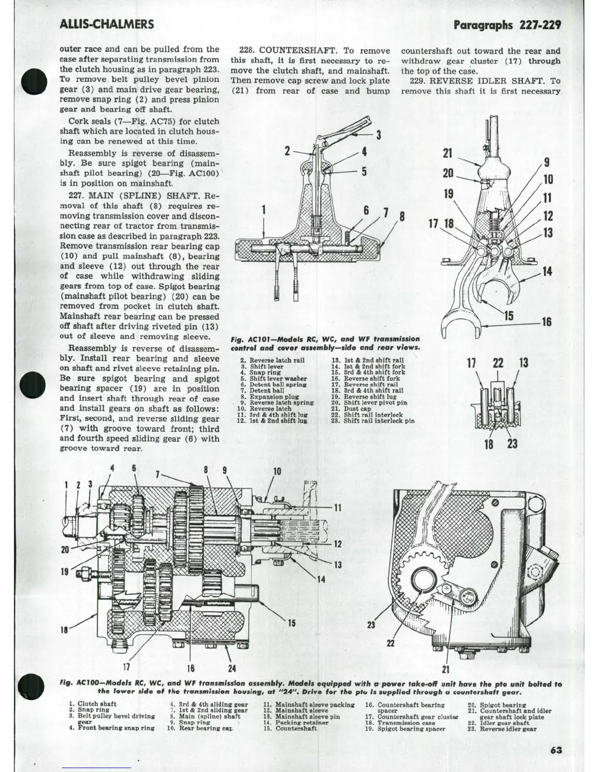
Fig, AClOl-Models HC, WC, and WF transmission
control and cover assembly^side and rear views.
17
18
16
10.
11.
12.
Reverse
latch rail
Shift
lever
Snap
rine
Shift
lever washer
Detent
ball sprins
Detent
ball
Expansion
plug
Reverse
latch spring:
Reverse
latch
3rd &
4th shift lus
1st &
2nd shift lug
13.
1st
&
2nd shift rail
14.
1st
&
2nd shift fork
16.
3rd
&
4th shift fork
16.
Reverse shift fork
17.
Reverse shift rail
15.
3rd
&
4th shift rail
19.
Reverse shift lug
20.
Shift lever pivot pin
21.
Dust cap
22.
Shift rail interlock
23.
Shift rail interlock pin
18
23
1
2
13
IS
24
22
Fig, AClOO^Models ftC, WC, and WF
transmissiton
assembly.
Models equipped with a power take-off unit have the pto unit bolted to
the lower side of the transmission housing, at "24". Drive for the ptu Is supplied through a countershaft
gear.
U
Clutch shaft
2.
Snap ring
3.
Belt pulley hevel driving
gear
4.
Front bearing snap ring
6. 3rd
&
4th sliding gear
7.
1st
&
2nd sliding gear
8. Main (spline) shaft
9.
Snap ring
10.
Rear bearing cap
11.
Mainshaft sleeve packing
12.
Mainshaft sleeve
13.
Mainshaft sleeve pin
14.
Packing retainer
15.
C!ountershaft
16.
Countershaft bearing
spacer
17.
Countershaft gear cluster
18.
Transmission case
Id. Spigot bearing spacer
20.
Spigot bearing
21.
Countershaft and idler
gear
shaft lock plate
22.
Idler gear shaft
23.
Reverse idler gear
63